There are three general sources from which we create model geometry in a CAD software product:
- From a concept in our minds,
- From an existing printed drawing,
- From analysis and measurement of an existing product, perhaps that of a competitor in our industry.
Traditional CMM technology using touch or scanning probes is often combined with other measurement technology today. This includes laser, video, or white light sensors to provide what is known as multi-sensor measurement. Primarily, scanning output is in one of two major formats: point data and polygon data but the file format can come out as:
- IGES,
- DXF,
- ASCII,
- .stl,
- Steinbichler,
- VRML,
- or others.
1. Point data from a “.pts” file


In these two approaches to reengineering the geometry, NX offers tools to accommodate ease of use and accuracy. For point data, the user can create a new part file and choose the Points From File command under the File drop down of the Menu Bar.

For polygon data, 3D printer format (also known as stereo lithography or “.stl”), or facet body, the user can either open the foreign file format directly with the File->Open command or they can import the data into an existing NX part file
USING POINT DATA
Traditional Surfacing Commands
Since the early days of Unigraphics, there have been commands to accommodate the creation of surfaces by defining either point locations or pole locations. Both commands (from the Insert->Surface Menu Bar drop down) provide a means of importing and creating in one step using a “Points from File” option. Additionally, each method also allows the individual selection of points in rows.


Once the point data resides in the NX part file, various methods are used to use this data in creating surface and solid bodies. A highly efficient command called Fit Surface (new in NX8.5) allows the user to generate a single surface from all or a portion of the points in one step. The points must first be grouped into a set using the command Format->Group->New Group.The drop down option at the top of the dialog offers analytic as well as freeform options.


The process involves the selection of points, a Fit Direction options selection, and an optional step for defining a 4-sided boundary. The level of Parameterization is accommodated with the selection of degree and patches in both the U and V directions of the intended surface. The Smoothing Factor is an approximation control which allows greater or lesser deviation from the actual point locations with the resulting surface having less radical changes in curvature and contour.

Using Curve Construction Tools
Another approach to using the point data, again more traditional, is to create curves (lines, arcs, conics, and splines) from the points near the edges of the intended surface or solid geometry boundaries and then create the surface (sheet) or solid bodies from the curves. The full suite of Freeform tools in NX provides nearly endless solutions to accommodate this approach including:
- Ruled,
- Through Curves,
- Through Curve Mesh,
- N-sided,
- Sweep Along Guide,
- Swept,
- Variational Sweep,
- etc.
USING POLYGON DATA
Rapid Surface Technology
A newer approach that utilizes the polygon (facet or .stl) types of data allows the user to break down the polygon surface areas into general shapes, ideally somewhat analytical in nature but freeform contours are completely acceptable.
 |
| Rapid Surface Creation Process |
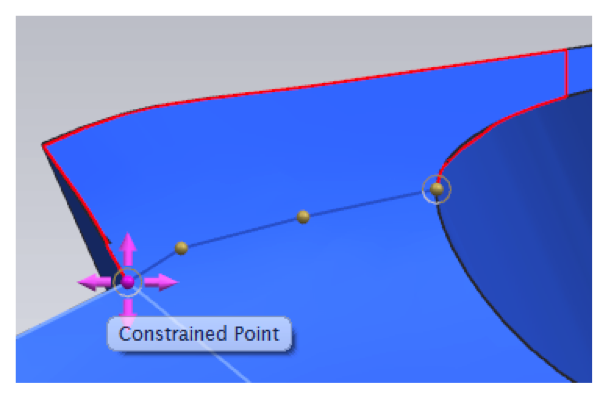 |
| Creation of Individual Sheet Edges |
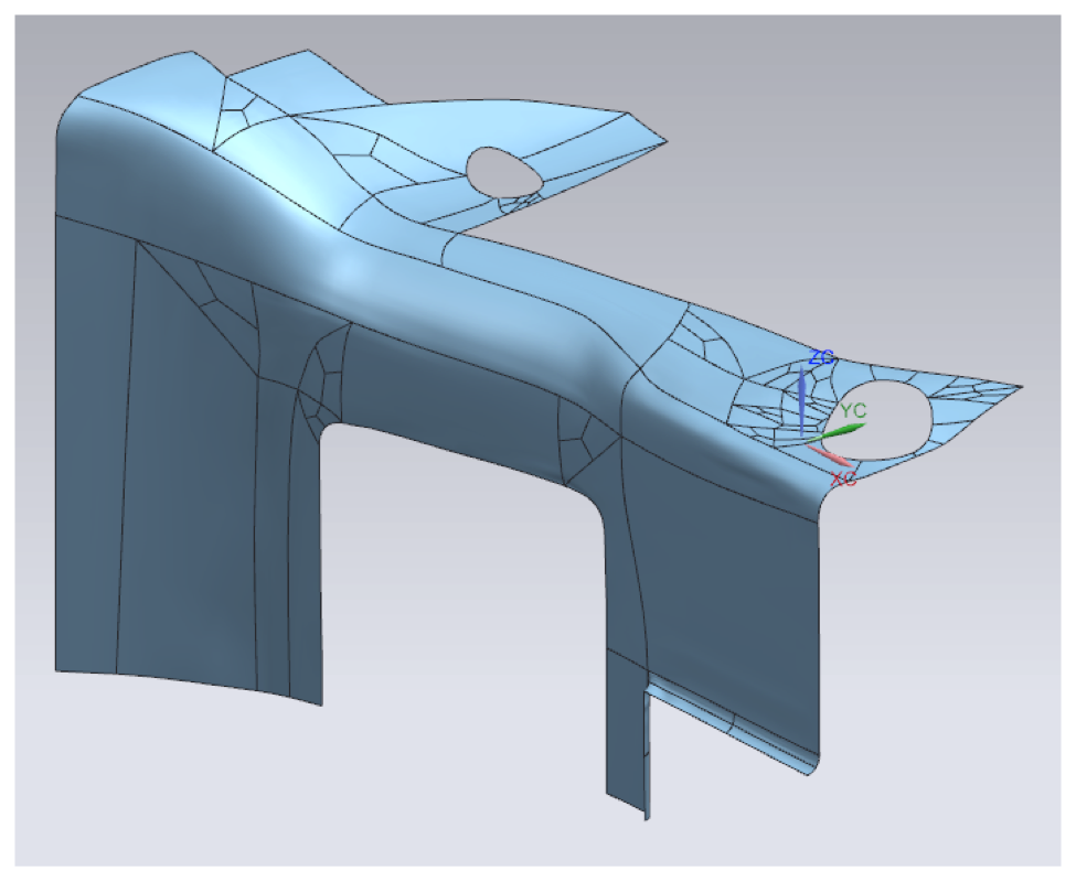 |
| Resulting Surfacing in Sheet Bodies |
This process is clearly shown, along with other forms of adapting and using facet geometry in the following video.
SUMMARY
Reengineering can be accomplished in many ways and the results are, like many other tasks, always a result of the source data and techniques used. From the techniques shown above, users are able to generate newly engineered parts that can serve as the base model for additional parametric features or can be modified with Synchronous Technology. Hopefully this report provides insight into the many methods that NX can be applied to reengineer existing products.
By Garrett Koch, Application Engineer, Swoosh Technologies & Solutions
Capsule theory is an excellent concept to talk about, but you can't ignore the relation of capsule theories with Big data solutions developer.
ReplyDelete