Thursday, May 29, 2014

Solid Edge ST7 packed with Hundreds of Customer Requested Enhancements

Solid Edge University 2014, held during the week of May 12th in Atlanta, brought the launch of Solid Edge ST7. The most powerful Solid Edge yet is updated with hundreds of enhancements requested from you, the user, that allow you to accelerate your 3D modeling, streamline your design management, power up with new apps, and enjoy a user friendly experience.

Solid Edge has always lent its hand to aiding users to design faster and ST7 is no different. 3D Sketch, available in the part, assembly and sheet metal environment, speeds up modeling by rapidly defining 3D paths for sweep operations. 3D Sketch also allows you to model pipes and wires that are bent in more than one plane, and in the assembly environ¬ment for the definition of exact paths for piping, wiring and tubing.


Solid Edge ST7 speeds up the modeling of massive assemblies. Design faster and more flexibly by duplicating components or patterning components along a curve. Performance is faster in massive assemblies and now gives users the control over the extent to which the assembly is recomputed during open and save operations.


ST7 users now have the ability to create photorealistic renderings with integration of KeyShot. KeyShot is the easiest and fastest rendering software that allows users to produce beautiful product images and processes concurrently with modeling operations.  Any changes to the model are automatically updated in the rendered image using the “Live Link” capability with no need for you to reassign materials, set up animations again or update any other settings.

Solid Edge SP, a SharePoint based data management solution received a facelift in the latest release. Visualizing data and assemblies has never been easier. Quickly create workflows for task completion and show multiple property cards at once.

    
Solid Edge is part of a growing ecosystem of apps designed to increase productivity, manufacturing, and collaboration capabilities. These apps allow for mobile access to standard and catalog parts, automated output of models for 3D printing, expanded manufacturing abilities, cloud-based collaboration, and more. This includes CAMWorks for Solid Edge and CADENAS PartSolutions. View the apps available here.

Solid Edge ST7 brings a more intuitive user interface resulting in a faster learning curve and improved efficiency. A visual startup page provides easier access to templates, recent documents, instructional videos, the online community and standard parts. Learning paths that meet the needs of specific users are easier to access, and an improved 3D orientation “quick view cube” enables you to quickly understand model orientation and jump to common views.

Look for our What’s New in Solid Edge ST7 webinar coming soon!

Start your free trial of Solid Edge here.

Candis Spraul
PLM Marketing Specialist
Swoosh Technologies


Wednesday, May 28, 2014

Aerospace consultant helps customers make smart design decisions early in the development process

Aerospace consultant, Noesim, automates its CAE process with Femap from Siemens PLM Software, from simulation model generation to analysis and final reporting. Other results included reduced finite element modeling time, early design validation and reduced prototyping costs for customers. The company designs structural parts, manufacturing tooling and ground maintenance equipment.

Learn more here.

Start you 45 day free trial of Femap here!

Food processing machine maker achieves 63 percent design productivity gain

Reading Bakery designs better with Solid Edge. Detailed drawing production time was reduced from 3.2 hours to 1.2 hours and designers produced three times as many drawings the first year as it had using its old 2D CAD. With Solid Edge’s built-in data management system, about half of all employees (manufacturing, purchasing, sales, CNC shop) can access current design data.

Learn how here.

Start your 45 day free trial here.

How to Use Variable Tables in Solid Edge

Solid Edge has the capability of using a Variable Table to help define and edit functional relationships between variables and dimensions of a design in a familiar spreadsheet format.  This tool can be leveraged to automate your design process. This article gives a basic overview of how the table functions and how to incorporate values from an external spreadsheet to drive a design. If you have a programing background, you can even create your own VB script and take your automation to a whole different level.

Basic Variable Table

Here is a simple design of a block with the some basic dimensions. To begin using the Variable table you must have the dimensions that you wish to control “locked” (They will be displayed as red).


To get to the Variable Table go to the Menu Ribbon and select Tools and then Variables.


In the Variable Table you will see all the data that is associated with the design. In this table you can see the variables and dimensions, names, values, rules, formulas, and other columns. Here we renamed the dimension names from the Solid Edge default of Linear_* to Height, Length, and Width making it easier to identify. Also see the locks allowing you to go in and edit the Formula columns. If these were unlocked this option would not be available.


 Now you can drive the design from here.  By double clicking the Value cell, you can change the dimensions in real time. The Formula column can also be used to add a formula to drive a dimension that in-turn drives the design. This example shows a very simple formula; you can get as complex as you want by adding in your own variables and using them in your formulas. 

If you right click on a value, and select the Variable Rule Editor you can control the values to limit it to a list of specific values or you can set a min/max limit. See the video below.


Excel Spreadsheet

You can also drive a design from an external Excel spreadsheet. Here is another block setup with some locked dimensions and a cutout that is constrained to the center block. A spreadsheet with some dimensional values with driving formulas has also been created.


Inserting the data into Solid Edge is as easy as copy and paste. Once the link is pasted, you can drive the design directly from the spreadsheet (just as above from the variable table). With the spreadsheet, your imagination is the limit. You can utilize all the power of Excel: macros, formulas, and programing. We have customers creating whole product lines from one single spreadsheet. See the video below for an example:


This is just scratching the surface. Using this tool Solid Edge and/or extra options that Excel or Visual Basic offer, you can really accelerate your design.

Looking for training in Solid Edge? Check out the current training schedule or request a class here.

Sam Estrada
Application Engineer
Swoosh Technologies

Thursday, May 22, 2014

How to Download Siemens Software from the Swoosh Technologies Customer Portal

Swoosh Technologies' customers get exclusive access to the customer portal. Here customers can download the latest Siemens PLM software. Follow the steps below to register as a user and get started using your software today!

First, you will need to register for an account. Go the Swoosh Technologies website here. Click the link to the customer portal.


Click 'Create new account.'

Fill out the required fields in the customer log-in form and click the Create New Account button at the bottom of the form. A Swoosh Technologies representative will receive your request and activate your account. This is usually accomplished within the same day of the request, but may take up to 72 hours.

You will receive email notification when your account is activated.

Return to the log-in page and enter your log-in information. You will need your username and password.

Click on the Siemens PLM Downloads on the left hand side of the web page.


In the drop down menu, select the desired software version and click Submit.

Locate the software you wish to download and click Link to Patch. Note that there may be separate 32-bit and 64-bit downloads.

Remember to log out when finished.

Garrett Koch
Application Engineer
Swoosh Technologies

Wednesday, May 21, 2014

Packaging machine manufacturer achieves 70 percent reduction in product development time

Uflex Engineering designs better with Solid Edge. The company designs and manufactures printing, packaging and converting machines. The engineering division also achieved significant financial benefits, reduced design errors and rework, delivered more accurate cost estimates and lowered the price of its machines.

Learn more here. 

Start your free trial of Solid Edge here.

Tuesday, May 20, 2014

NX How To: Set up the Reuse Library for Custom Symbols

Follow these steps to set up the Reuse Library in NX 9 for custom symbols:

Go to the customer defaults dialog box. 

In the Gateway portion, click Reuse Library, and map the location to your symbol files.


NOTE: The files that contain your symbols must be contained in the folder that you map inside the customer defaults.

Below is a screen shot of the location I have mapped in my defaults file (click the image to enlarge). here you can see the file containing my symbol.


To create a symbol, first right click on the Library where you want your new symbol to reside and click Define Custom Symbol.

The Define Custom Symbol dialog box now appears. Follow these steps to upload a new symbol:

1. Change the folder you wish to store the custom symbol inside.
2. Name the Symbol and name the part in the symbol folder.
3. Select the objects of the symbol.
4. Select the Anchor point to the symbol. The anchor point is the point that controls the placement of the symbol.
5. Finally select the image you wish to display of the symbol. It can be a screen shot of the graphics area or it can be a BMP or JPG file with different resolutions.

Note:  If properly executed your symbol should appear as shown below.

Learn more about NX with training from Swoosh Technologies! View the upcoming courses here.

Brian Brown
Application Engineer
Swoosh Technologies

Wednesday, May 14, 2014

Material handling systems provider cuts development time 20 percent

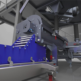
Cybernetik Technologies designs better with Solid Edge. Synchronous technology is also credited for cutting costs by 20 percent through higher design accuracy. Design errors dropped by nearly 30 percent and Cybernetik was better able to convey design concepts and wins new customers.

Learn how here.

Start your 45 day free trial of Solid Edge here!

Wind turbine design accelerated in Europe’s windiest country

With Femap Composite structural engineering consulting firm PlySim achieves 500+ percent modeling improvement for wind turbine blades and expands worldwide contracts. "[Femap] is a tool that will do everything you want at a much lower price compared to its nearest functional competitors," said Malcolm Wadia, director, PlySim.

Learn how here.

Start your free trial of Femap here.

Wednesday, May 7, 2014

Bakery Equipment Manufacturer Shrinks Design Time 50 Percent

AMF Canada designs better with Solid Edge. With design time down 50 percent, other results included a key reduction and near elimination of sheet metal rework. Assembly times dropped 20 percent and the food processing machinery company was able to meet critical delivery times.

Learn how here.

Start your 45 day free trial of Solid Edge here!

Tuesday, May 6, 2014

How to Modify your Post Processor for On Machine Probing in NX 9

What is On Machine Probing?

On machine probing is a measurement technique used on machine tools to use while your part is still in process on the machine.

The machine uses a 2D or 3D probe similar to those found on some CMM’s. The end of the probe sensor that comes into contact with the part is made of hard non-marring material for metals such as a ruby.

The probe contacts the part and records the machine position when the probe sensor is triggered.  Probe positions are recorded on the controller, and the probe point positions may be processed directly after the points are taken or later to obtain meaningful data from the points.  The meaningful data can then be relayed to the operator, quality system, or back for adaptive part processing. Machine tool probes may be obtained through Renishaw or other manufacturers.

Why should you use it?
  • Prevents the use of additional CMM’s
  • Increases machine tool accuracy
  • Ability to buy off part while still fixtured in the machine
  • Easily obtain spc data
  • Reduce Gage tooling cost
  • Faster than traditional measurement and reduces human error
What is required in NX to use it?
  • Renishaw Probing hardware installed on machine
  • Renishaw Inspection Plus Macros
  • NX CAM MACH package 9.0 or higher
  • Supported post
  • NX CAM on machine probing is supported for both Fanuc and Siemens Sinumerik controllers
View the video below to discover how to modify a post for on machine probing in NX.


Matt Beisel
Application Engineer
Swoosh Technologies