Monday, December 30, 2013

KeyShot Animation for 3D Models

KeyShot allows users to animate 3D models quickly and easily.  Models will be ready for presentations or assembly instructions in minutes. Keyshot does not rely on keyframes, but rather allows users to apply transforms (rotations, translations, etc) to set up new animations at the click of a button.


Check out some of our favorite animations below and get started with a free trial of KeyShot here.


Thursday, December 26, 2013

Solid Edge How To: Hidden Presets for Flattened Sheet Metal Parts

When creating flat patterns in 
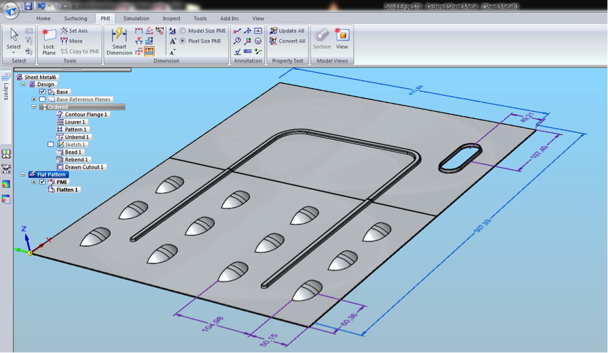
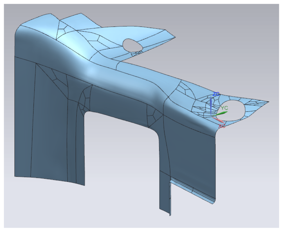
Solid Edge many options can be preset to speeding up design processes. In the sheet metal model shown in Image A , numerous deformation features including louvers, a drawn cutout, 
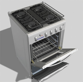
and a strengthening bead exist. Several options can be preset to either have these features show as is or as a flattened sheet metal part (Image B).
 
Image A

Image B
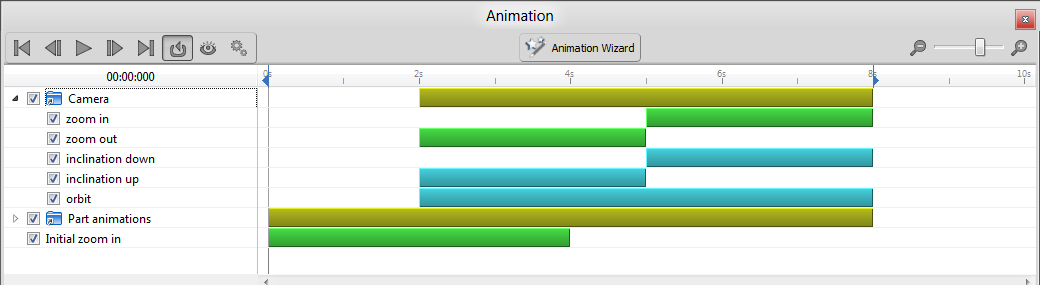
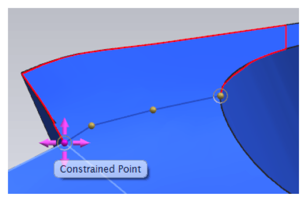
Another possibility exists to show where the deformation features are located in the flat but not necessarily show the actual features. Shown in the image below you will notice that the edge lines of the features are shown as well as the X, Y location of the center of the geometry.

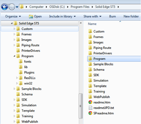
Navigate to the Application settings to locate find the options for flat treatments.


Notice other settings for the flattened models such as the options for adding corner breaks either radiuses or chamfers at the exterior or interior corners (Image E). Instead of taking the time to add corner treatments to a design, you have a single setting that will automate this.
Image E

For those who require a flat 2D DWG these setting export to the Save As Flat which has its own set of options such as including or excluding layers and exporting back to ACAD 12 DWG.


There is also a hidden gem for flattening an inserted part copy of a sheet metal part. It may be the “old-school” way of flattening a part for post processing, but there are commands that allow the actual flat sheet metal part to have post processing completed (Image G).


Dylan Malek
Application Engineer
Swoosh Technologies


Wednesday, December 18, 2013

Digital Process Speeds the Creation of Quality Consumer Products


Esmaltec designs better with Solid Edge. Consumer products maker's Solid Edge use reduces prototypes by 40 percent and rework by 80 percent. Its integrated development platform (Solid Edge and Teamcenter software) contributed to a 90 percent reduction in project deviations.

Learn more here

Sign up for your free trial of Solid Edge today! 

Tuesday, December 17, 2013

Solid Edge How To: Install Multiple Versions of Solid Edge

New with Solid Edge ST6, you can now have multiple versions installed on your workstation. This is useful if you want to do program testing or if you wanted to keep files in an older format. Using multiple versions is not for everyone; Siemens recommends if you are working inside of a production environment, that you only have a single version of the product installed. This is because add-on products like Mold Tooling, SE Teamcenter Client, and Solid Edge SP will not work correctly. Therefore, before you attempt this type of installation please check with your IT department, and read and understand the Solid Edge Installation Guide. This blog post will cover the installation of ST5 and ST6.

NOTE: These instructions are for Windows only.


Let’s get started!
 

For the multiple version installation to function correctly, you must have either ST5 or ST4 installed on your workstation first before you install ST6. Do not install a different 32/64 bit version of Solid Edge; if you have a 32bit version installed, the newer version must be the same bit version. The older version is a standard installation and should be done as per the Installation Guide.


Have the older version installed first


Once ST5 has been installed, you are ready to install ST6 using the “Silent Installation” method. If you try to install it using the standard installation produces, you will receive an installation error. To begin the process, open up the “Administrator Command Prompt”. To run this go to your start menu, select the “Accessories” folder, locate the “Command Prompt” program, and right-click on the icon. From the drop down menu, select “Run as Administrator”. This will launch the admin command prompt and will ensure you have the necessary rights to proceed with the silent installation.


You will use this window to run the command string that will install ST6 with the correct install parameters. At this point you need to ensure that you have your ST6 installation media loaded or you have it located on your hard drive. Below is the out of the box command sting that will kick off the silent install:

msiexec /i "<drive_letter>or<local_disk_location>:\Solid Edge\Solid Edge ST6.msi" MYTEMPLATE=3 USERFILESPECXML="C:\temp\My Docs\SEAdmin\Options.xml"
USERFILESPEC="C:\License Files\Network\ST6\selicense.dat"
INSTALLDIR="C:\Program Files\Solid Edge ST6" /qn+ /l*v "C:\temp\mysilentsetup.log"

You will need to modify this command before you execute the command. Copy the command text into Notepad (or similar program) and make the necessary changes there. When you are finished, you can copy and paste it into the command prompt.
 

Use these tips to customize this text:
  • <drive_letter>or<local_disk_location> Enter the correct location of the installation media, ie drive letter or if you have the installation files on your hard drive that location. 
  • MYTEMPLATE - is going to set the default templates in ST6, default is “3” 

  • USERFILESPECXML - is used if you have a specific set of Solid Edge custom options you would like to install with the new version; you can point to the “Options.xml” file located on your hard drive. This is optional
  • USERFILESPEC - can point to the license file that will be associated with the version being installed. This is optional, and a license file can added later using the License Manager.
  • INSTALLDIR - is going to set the installation location of ST6, ensure that the install path defined is different from the other version of Solid Edge already existing on your workstation
  • C:\TEMP\MYSILENTSETUP.LOG - will create a log file of the installation in your temp directory.
Here is an example of the command string used on my installation:
msiexec /i "C:\Swoosh Files\Solid Edge ST6 Program\SEST6_64_100\Solid Edge ST6.msi" MYTEMPLATE=4 INSTALLDIR="C:\Solid Edge ST6" /qn+ /l*v "C:\temp\mysilentsetup.log"


Once you have your command string ready, copy it out of Notepad and paste it into the Command Prompt that you have open.

After you execute the command (press enter), there will be no indication that the install is running. The installation will run in the background until complete, in which case it will inform you if it was successful or not.


If there was a failure, you can access the install log file that was created during the install process. Refer to the last line of the command string for the log file location.


When complete, navigate to the install directory and verity that ST6 was installed with all of its components, and if you like, create a shortcut to the EDGE.exe on your desktop.


At this point, if you did not link a license file to ST6, go to your start menu, locate the Solid Edge ST6 folder, Licensing, and run the License Utility to link it to your ST6 license file. 


 Now that you have two Versions of Solid Edge on your workstation, you still need to copy the “Set Active Solid Edge Version” application located on your installation DVD. Explore the DVD and navigate to this folder “<disk_drive>:\Solid Edge\SptTools\SESetActiveVersion” 


Copy this folder to your workstation. Then open the folder and create a shortcut to the “SESetActiveVersion.exe” on your desktop.
                                                              

You will be able to use the “SESetActiveVersion” application to switch between active versions of Solid Edge. To activate a version, select the desired option from the drop down list and click “Activate.” If you do not set the correct version, you may encounter some program errors.


Note: If you need to uninstall Solid Edge from your workstation, it is recommended that you uninstall all versions of Solid Edge and reinstall the production version from scratch. The possibility of corruption of the remaining versions exists following the uninstall of one version of Solid Edge.
 
Good luck and happy designing!

By Sam Estrada, Application Engineer, Swoosh Technologies & Solutions

Thursday, December 12, 2013

Reengineering Model Data in NX

Reengineering describes the process of creating a newly engineered design from a previously complete design, or to “engineer again”, as Merriam-Webster states. However, in the CAD/CAE environment the task can be much more complex than simply developing a product design from scratch as a -1 revision. The capture of physical geometry for shape, size, and location is accomplished by many different processes, machines, and software applications.

There are three general sources from which we create model geometry in a CAD software product:

  1. From a concept in our minds,
  2. From an existing printed drawing,
  3. From analysis and measurement of an existing product, perhaps that of a competitor in our industry.
The latter method involves the practice of reengineering and is growing in business processes and expanding into a diversity of machine technology, computer software, and industry standards. Machines designed to “feel” the features and characteristics of a part have been in a process of refinement for decades. The Coordinate Measuring Machine (CMM) has been developing more accurate and robust output since its inception in the 1950’s. New file formats came into play as each manufacturer and data collection and reduction system improved the assessment and probing technology. And thus, we arrive at the focus of the reengineering effort – reusing this data.

Traditional CMM technology using touch or scanning probes is often combined with other measurement technology today. This includes laser, video, or white light sensors to provide what is known as multi-sensor measurement. Primarily, scanning output is in one of two major formats: point data and polygon data but the file format can come out as:

  • IGES, 
  • DXF, 
  • ASCII, 
  • .stl, 
  • Steinbichler, 
  • VRML, 
  • or others.
Siemens NX (formerly Unigraphics) software is able to utilize both point and polygon scan data types and the different file formats, bringing them directly into an NX part file.

1. Point data from a “.pts” file


2. Polygon data from an “.stl” file


In these two approaches to reengineering the geometry, NX offers tools to accommodate ease of use and accuracy. For point data, the user can create a new part file and choose the Points From File command under the File drop down of the Menu Bar. 


For polygon data, 3D printer format (also known as stereo lithography or “.stl”), or facet body, the user can either open the foreign file format directly with the File->Open command or they can import the data into an existing NX part file


USING POINT DATA

Traditional Surfacing Commands

Since the early days of Unigraphics, there have been commands to accommodate the creation of surfaces by defining either point locations or pole locations. Both commands (from the Insert->Surface Menu Bar drop down) provide a means of importing and creating in one step using a “Points from File” option. Additionally, each method also allows the individual selection of points in rows.


Fit Surface Command

Once the point data resides in the NX part file, various methods are used to use this data in creating surface and solid bodies. A highly efficient command called Fit Surface (new in NX8.5) allows the user to generate a single surface from all or a portion of the points in one step. The points must first be grouped into a set using the command Format->Group->New Group.
The drop down option at the top of the dialog offers analytic as well as freeform options.
 
The process involves the selection of points, a Fit Direction options selection, and an optional step for defining a 4-sided boundary. The level of Parameterization is accommodated with the selection of degree and patches in both the U and V directions of the intended surface. The Smoothing Factor is an approximation control which allows greater or lesser deviation from the actual point locations with the resulting surface having less radical changes in curvature and contour. 


The results of these commands yield patches of the surfacing that can then be trimmed and sewn or combined with other commands like Face Blend, Bridge, Section, etc. Once adapted and manicured to completely enclose a volume, the sew operation will transform the surfaces into a single solid body.

Using Curve Construction Tools
 
Another approach to using the point data, again more traditional, is to create curves (lines, arcs, conics, and splines) from the points near the edges of the intended surface or solid geometry boundaries and then create the surface (sheet) or solid bodies from the curves. The full suite of Freeform tools in NX provides nearly endless solutions to accommodate this approach including: 

  • Ruled, 
  • Through Curves, 
  • Through Curve Mesh, 
  • N-sided, 
  • Sweep Along Guide, 
  • Swept, 
  • Variational Sweep, 
  • etc.

USING POLYGON DATA

Rapid Surface Technology
 

A newer approach that utilizes the polygon (facet or .stl) types of data allows the user to break down the polygon surface areas into general shapes, ideally somewhat analytical in nature but freeform contours are completely acceptable.

 Rapid Surface Creation Process

Creation of Individual Sheet Edges
Resulting Surfacing in Sheet Bodies


This process is clearly shown, along with other forms of adapting and using facet geometry in the following video.


SUMMARY

 
Reengineering can be accomplished in many ways and the results are, like many other tasks, always a result of the source data and techniques used. From the techniques shown above, users are able to generate newly engineered parts that can serve as the base model for additional parametric features or can be modified with Synchronous Technology. Hopefully this report provides insight into the many methods that NX can be applied to reengineer existing products.

By Garrett Koch, Application Engineer, Swoosh Technologies & Solutions

Wednesday, December 11, 2013

Faster Modeling Accelerates Powerwing Redesign

Razor USA designs better with Solid Edge. Scooter and battery-powered ride-on toy maker reduces part design time with synchronous technology from one week to two days and makes design changes in seconds vs. hours when compared to traditional history-based modeling.

Learn how and watch the video here.

Start a 45 day free trial of Solid Edge here!

Wednesday, December 4, 2013

Automotive Fixture Design Cycle Cut Nearly in Half

Melling Tool designs better with Solid Edge. Manufacturer of tooling for oil pump and other power train components uses synchronous technology to cut design time from four to two weeks when compared with traditional history-based design.

Learn more here!

Start a free trial of Solid Edge today!