Siemens PLM’s Solid Edge team is sponsoring another great challenge hosted by GrabCAD! This is your chance to trick out the Razor Crazy Cart by Razor USA to showcase your creativity, quality of design and design thinking. Simply download models, start designing, create a render and animation using Solid Edge and KeyShot, and submit it online.
If you are not a current Solid Edge user, start your 45 day trial here for your opportunity to win!
If you currently use Solid Edge, but want to show off your design with KeyShot’s amazing photo-realistic rendering capabilities, start your trial of KeyShot here.
You could win a Microsoft Surface Pro 3, a subscription of Solid Edge
Premium with KeyShot Pro and Animation and a Razor Crazy Cart! Click
here to view the details and submit your design today!
Thursday, October 16, 2014
Wednesday, October 15, 2014
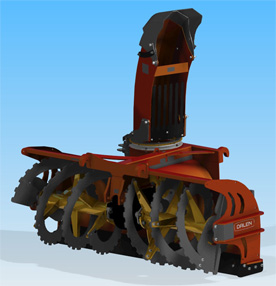
Forestry and agricultural products maker enhances product quality and durability
Lid Jarnindustri designs better with Solid Edge. As a result, the company is now able to compete with low-cost suppliers. It has enhanced customer service, increased speed for altering product design, improved communication between customers, designers and its production line, and reduced the number of physical prototypes.
Learn how here.
Start your 45 day free trial of Solid Edge here.
Learn how here.
Start your 45 day free trial of Solid Edge here.
Labels:
case study,
Solid Edge
Location:
St. Louis, MO, USA
Innovative aircraft propeller manufacturer leverages finite element analysis for materials testing
Aircraft propeller manufacturer MT-Propeller develops better products using Femap from Siemens PLM Software. Results include reducing prototype testing, improving manufacturability and increasing sales.
"Based on our finite element analysis (technology), we were able to reduce stress by a third," said Martin Albrecht, MT-Propeller CEO.
Learn how here!
"Based on our finite element analysis (technology), we were able to reduce stress by a third," said Martin Albrecht, MT-Propeller CEO.
Learn how here!
Location:
St. Louis, MO, USA
Tuesday, October 14, 2014
Halloween fun with Solid Edge ST7 and KeyShot
In celebration of Halloween, I thought a Jack-O-Lantern would be fun to replicate in Solid Edge ST7 and to compliment the design, a cool render from Keyshot.
The first phase of my pumpkin creation resided around the creation of easily synchronous sketched curves to dictate the size of the pumpkin. Synchronous made this step easy using the steering wheel and patterning to replicate and modify the sketches.
Next I used Blue Surfing to bring the edges together and inserted sketches along the way - eventually resulting in a solid body shown in the image below. Watch the video below this creation in real time.
Once I had a solid body, which made up the Jack-O-Lantern body, the following parts were very easy to create. Using a part and doing a Multi Body design made it easy to create the top for the lantern.
After all the parts were designed and published to an assembly, all the rendering fun starts in KeyShot! After having sent the Solid Edge model to Keyshot, spending a few minutes of adding lights, an iron bumpmap, and adjusting a few artistic settings such as view focus and setting vignette strength, its time for a render.
Have some fun and share your Halloween designs in a comment below. Happy rendering!
Dylan Malek
Application Engineer
Swoosh Technologies
Start your 45 day free trial of Solid Edge integrated with KeyShot here.
The first phase of my pumpkin creation resided around the creation of easily synchronous sketched curves to dictate the size of the pumpkin. Synchronous made this step easy using the steering wheel and patterning to replicate and modify the sketches.
Next I used Blue Surfing to bring the edges together and inserted sketches along the way - eventually resulting in a solid body shown in the image below. Watch the video below this creation in real time.
Once I had a solid body, which made up the Jack-O-Lantern body, the following parts were very easy to create. Using a part and doing a Multi Body design made it easy to create the top for the lantern.
 |
| Close up of Iron bumpmap on SE color vs standard SE color alone. |
Have some fun and share your Halloween designs in a comment below. Happy rendering!
Dylan Malek
Application Engineer
Swoosh Technologies
Labels:
Dylan Malek,
KeyShot,
Solid Edge ST7
Location:
Dallas, TX, USA
Tuesday, October 7, 2014
Add a Custom Command for Header Lines for Post Processing in NX 9 CAM
Follow these simple steps to create a Custom Command in NX CAM to add to a post processor for header lines to be output from a post processor:
Start Postbuilder.
Select the custom command tab.
Select the Create option.
Right mouse button on the new custom command and rename it. To PB_CMD_header line.
Highlight everything in the right window, as displayed below.
Once everything is highlighted, select the delete key.
Select the lines below:
#=============================================================
proc PB_CMD_header_line { } {
#=============================================================
#This Custom Command will output the header information
#this will output information associated with a program
global mom_oper_program
global mom_part_name
global mom_date
global mom_logname
MOM_output_literal "(PROGRAM NUMBER: $mom_oper_program)"
MOM_output_literal "(PART NAME : $mom_part_name)"
MOM_output_literal "(POSTED DATE : $mom_date)"
MOM_output_literal "(PROGRAMMED BY : $mom_logname)"}
Copy the lines selected above and paste them into the right side of the dialog box. It should appear like this:
Select the Program Tab.
Select the Program Start Sequence.
Select the name of the custom command you just created. In this case it should be the PB_CMD_header line.
Select the Add block option.
Drag the command after the rewind stop code.
This will add the header lines to the beginning of the CNC program.
Want to learn more about customizing your posts? Get training in NX CAM post processing from Swoosh Technologies. Learn more here!
Written by
Brian Brown
Application Engineer
Swoosh Technologies
Labels:
Brian Brown,
NX 9,
NX CAM,
Post Processing
Location:
Harrisburg, PA, USA
Wednesday, October 1, 2014
Labeling machine manufacturer optimizes material use, implements near error-free design process
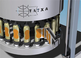
TATXA designs better with Solid Edge. TAXTA specializes in the production of labeling machines for the food, cosmetic and pharmaceutical industries, as well as for cleaning products and other special applications. Other results included reduced costs across operations, increased machine availability and opportunity, and improved product performance as well as product aesthetics.
Learn how here!
Start you r45 day free trial of Solid Edge here.
Learn how here!
Start you r45 day free trial of Solid Edge here.
Faster FEA reduces processing time for aircraft modeling and results
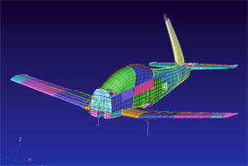
Aviation services provider Aquila Engineering uses Femap from Siemens PLM Software to save its customers tens of thousands of dollars and reduces prototyping and physical testing. Aquila meets key challenges to make aircraft modifications that meet regulatory requirements and remain cost effective.
Learn how here!
Learn how here!
Labels:
case study,
FEA,
Femap
Location:
St. Louis, MO, USA
Tuesday, September 30, 2014
The Improved User Interface in Solid Edge ST7
Solid Edge ST7 includes many enhancements that accelerate your 3D part and assembly modeling as well as the creation of 2D drawings. The latest version also includes excellent photo-realistic rendering capabilities that enable you to create beautiful images of your products. This blog article focuses on these enhancements starting with how ST7 helps you enjoy an amazing user experience.
The updated user interface enables an even faster learning curve than previous versions of Solid Edge also designed to improve efficiency for experienced users. Upon starting ST7, users see a visual startup page, which provides easier access to templates, recent documents, instructional videos, the Solid Edge online community, and standard parts including Cadenas and TraceParts.
To more easily and quickly understand your model orientation and jump to common views, ST7 provides an improved “quick view cube.” See this and more about the latest UI enhancements in the video below created by Swoosh Technologies’ Solid Edge instructor, Sam Estrada.
What’s covered in the video:
- Revamped Startup Page
- Access to Templates
- Recent Documents
- Expanded File Open Dialog
- Instructional Videos
- Learning Paths
- Online Community and Component Catalogs: Cadenas and TraceParts
- Highly Visual, in –window drawing tools
- Quick View Cube
- Visually appealing intuitive sketch drawing tools
- Graphical information in tooltips
- Enhanced tooltips with more text, graphics and videos
Labels:
Sam Estrada,
Solid Edge ST7
Location:
Houston, TX, USA
Wednesday, September 24, 2014
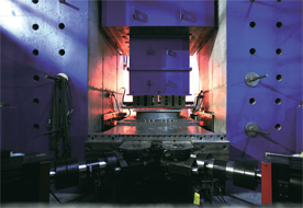
Hyundai Motor Co. reduces time and cost needed to design car body assembly lines
Hyundai Motors designs better with Solid Edge. The move from 2D to Solid Edge 3D provided a 20 percent design time reduction. Hyundai chose Solid Edge for its ease of use in solid modeling as well as the efficiency of its 2D drafting performance and integrated data management. Solid Edge helped increase quality and reduced repetitive tasks.
"By using Solid Edge to implement 3D CAD with design management, we have been able to effectively reduce design time and costs."
- Jung Hyun Seok, Assistant Manager, Automation Design Team
Learn how here!
Start you 45 day free trial of Solid Edge today here.
"By using Solid Edge to implement 3D CAD with design management, we have been able to effectively reduce design time and costs."
- Jung Hyun Seok, Assistant Manager, Automation Design Team
Learn how here!
Start you 45 day free trial of Solid Edge today here.
Tuesday, September 23, 2014
Working with Spreadsheet Data in NX 9
How can we use a spreadsheet to drive the design of an NX part?
NX part files can contain, reference, and link to spreadsheet data. This is often used to define iterations or multiple configurations of a design such as Pattern features, Part Families, etc. Methods such as Patterns generally retain the spreadsheet data within the feature definition and not the part file as in the case of Part Families. This article discusses the application and use of spreadsheet driven data from both perspectives.
Spreadsheet Overview
The Spreadsheet serves as an advanced expression editor for NX hybrid modeling thus providing a seamless transfer of conceptual model data between NX and the spreadsheet.
This section focuses specifically on the spreadsheet extensions and applications in NX and is intended to be a supplement to the standard spreadsheet documentation, which can be viewed in the NX Documentation Set.
The spreadsheet consists of three main session applications:
Gateway Spreadsheet
The Gateway spreadsheet is activated in current application modes except for Modeling.
NX will start a copy of Xess, or Microsoft Excel on Windows, and make connections to it automatically. Messages on the status line inform you of the progress made toward connecting with the spreadsheet. If there is a copy of the spreadsheet already running on your display that can accept connections, then NX uses that copy without invoking another instance of the spreadsheet.
Note:
Modeling Spreadsheet
The Modeling spreadsheet is launched by Tools→Spreadsheet and requires that the current application mode be in "Modeling".
NX will start a copy of the spreadsheet and make connections to it automatically. Messages on the status line inform you of the progress made toward connecting with the spreadsheet. If there is a copy of the spreadsheet already running on your display that can accept connections, then NX will use that copy without invoking another instance of the spreadsheet.
Note:
With the exception of the Reference Layout, a Spreadsheet option is available for all other layouts in the Pattern dialog. This allows the user to drive the design of the duplicated feature(s) to be driven by spreadsheet data. Once the feature to duplicate has been selected and the Layout requirements have been satisfied, the Use Spreadsheet option will become active.
NX allows the access of spreadsheet data directly from an outside file. There are two ways to do this, depending on what format you want.
1. Go to Tools→Import and Export Expressions, select the Import option, and browse for the spreadsheet file to bring in. You’ll note there are two formats you can filter for, “.xls” and “.xlsx”.
A listing window reports the success or failure of the imported expressions:
This process allows outside spreadsheet data in .xls or .xlsx format to be brought into an NX part file directly as expressions but without any linking or associativity.
2. Go to Tools→Expressions and in that dialog at the top there’s an icon for Spreadsheet Edit.
This will start a new spreadsheet and from there you can open an existing spreadsheet or copy/paste from another spreadsheet. NX doesn’t offer an Import Spreadsheet command under File→Import but that does not matter if you can just open an existing spreadsheet using this method. Once the Worksheet is open, note the ADD-INS tab at the top resulting from the NX integration for spreadsheets in the NX installation.
Next to the Spreadsheet Edit icon in that dialog, there are also two icons for Import Expressions from File and Export Expressions to File. These two functions allow the copying of an expressions file (with the extension of “.exp”) into or out of an NX part file.
With the use of the spreadsheet and expressions functions discussed above, the NX user has the ability to reuse mathematical values, formulae, expressions, equations, and even character strings both inside and outside of an NX part file. This functionality is practically identical when working with assembly or drawing files as well.
However, these practices do not develop any associativity or linking between the data within the NX part and that or the spreadsheet or expression file.
Procedure for linking a value in a spreadsheet outside of a part file to an internal expression:
1. Choose Tools tab→Utilities group→Expressions.
2. In the Expressions dialog box, in the Name box, type “thickness”.
3. Click Functions.
4. In the Insert Function dialog box, from the Or Choose a Category list, select spreadsheet.
5. From the list of functions, select ug_cell_read.
6. Click OK.
7. In the Function Arguments dialog box, click Specify a spreadsheet.
8. Navigate to the desired spreadsheet and click OK.
9. In the Specify a Cell box, type the desired cell callout such as “B3”.
The Expressions dialog box is displayed and the function ug_cell_read("<SPREADSHEET_NAME>", "B3") appears in the Formula box.
10. Click OK.
11. Verify the value of the expression and click OK.
Migrating data between spreadsheet applications (Excel/Xess)
To assist you with migrating data between spreadsheet applications, NX provides a migration utility.
Platforms
On Windows, you can migrate spreadsheet data from Xess to Excel and vice versa. On all systems, you don't need to have access to the spreadsheet where the data is stored. You only need access to the spreadsheet to which you are migrating.
Required Software
When migrating from Xess to Excel, you only need Excel. Similarly, migrating spreadsheet data from Excel to Xess requires only Xess (which also means that Exceed must be present).
Before You Begin
Before you begin, make a copy of the part containing the old spreadsheet data. Keep the copy until you verify that the new spreadsheet data is correct.
In this example, the value of the expression is 2.5.
Note: If the spreadsheet is modified, you can update the expression by clicking Refresh Values from External Spreadsheet.
Spreadsheets are also available in the Drafting application. As an example, a Tabular Note on a drawing can be edited using a spreadsheet. Simply right-click the handle of the Note and select Edit Using Spreadsheet from the popup menu.
Note that by default, Expressions functionality is not enabled in the Drafting application. It can be turned on either by editing the settings in the global customer defaults file (.dpv) or by going to File→Utilities→Customer Defaults→Drafting→Drawing→General tab, and toggle the Allow Expressions option on.
Written by
Garrett Koch
Application Engineer
Swoosh Technologies
Want to learn more about NX and improve your efficiency? Enroll in NX training or request a custom class or mentoring here today!
NX part files can contain, reference, and link to spreadsheet data. This is often used to define iterations or multiple configurations of a design such as Pattern features, Part Families, etc. Methods such as Patterns generally retain the spreadsheet data within the feature definition and not the part file as in the case of Part Families. This article discusses the application and use of spreadsheet driven data from both perspectives.
Spreadsheet Overview
The Spreadsheet serves as an advanced expression editor for NX hybrid modeling thus providing a seamless transfer of conceptual model data between NX and the spreadsheet.
This section focuses specifically on the spreadsheet extensions and applications in NX and is intended to be a supplement to the standard spreadsheet documentation, which can be viewed in the NX Documentation Set.
The spreadsheet consists of three main session applications:
- A Gateway spreadsheet function, available in Tools tab→Utilities group→Spreadsheet.
- A Modeling spreadsheet function, available from Tools tab→Utilities group→Spreadsheet. Some spreadsheet programs (such as " Goalseek"), may not be fully supported within the Modeling Spreadsheet extended functionality.
- A basic Expression Editor. You can find the expression edit spreadsheet in the Tools→Expression dialog in Modeling. Click "Spreadsheet Edit."
Gateway Spreadsheet
The Gateway spreadsheet is activated in current application modes except for Modeling.
NX will start a copy of Xess, or Microsoft Excel on Windows, and make connections to it automatically. Messages on the status line inform you of the progress made toward connecting with the spreadsheet. If there is a copy of the spreadsheet already running on your display that can accept connections, then NX uses that copy without invoking another instance of the spreadsheet.
Note:
- If there is already a spreadsheet saved in the part, then that spreadsheet will be opened with the application that created it (Xess or Excel) regardless of the default spreadsheet set in the spreadsheet preferences. If there is no spreadsheet stored in the part, and you are running on Windows, the setting from Preferences→Spreadsheet (available only on Windows) will be used to determine whether to use Xess or Excel.
- An Xess spreadsheet session started from a command line can accept connections to NX if you start the program with the command line options "-connect a" or if you toggle the Connections→Accept Connections option on the spreadsheet main menu bar. Remember that the NX specific version of Xess, xessu, cannot be started from the command line.
Modeling Spreadsheet
The Modeling spreadsheet is launched by Tools→Spreadsheet and requires that the current application mode be in "Modeling".
NX will start a copy of the spreadsheet and make connections to it automatically. Messages on the status line inform you of the progress made toward connecting with the spreadsheet. If there is a copy of the spreadsheet already running on your display that can accept connections, then NX will use that copy without invoking another instance of the spreadsheet.
Note:
- If there is already a spreadsheet saved in the part, it will be opened with the application that created it (either Xess or Excel), regardless of the default spreadsheet set in its preferences. If there is no spreadsheet stored in the part, and are running on Windows, the setting from File tab→Preferences→Spreadsheet will be used to determine whether to use Xess or Excel.
- In these discussions about the Modeling spreadsheet, the pull-down menus such as File→, Edit→, and Tools→ usually refer to options within the spreadsheet, not the pull-down menus from the NX main Menu Bar (unless specified).
With the exception of the Reference Layout, a Spreadsheet option is available for all other layouts in the Pattern dialog. This allows the user to drive the design of the duplicated feature(s) to be driven by spreadsheet data. Once the feature to duplicate has been selected and the Layout requirements have been satisfied, the Use Spreadsheet option will become active.
1. Go to Tools→Import and Export Expressions, select the Import option, and browse for the spreadsheet file to bring in. You’ll note there are two formats you can filter for, “.xls” and “.xlsx”.
A listing window reports the success or failure of the imported expressions:
This process allows outside spreadsheet data in .xls or .xlsx format to be brought into an NX part file directly as expressions but without any linking or associativity.
2. Go to Tools→Expressions and in that dialog at the top there’s an icon for Spreadsheet Edit.
This will start a new spreadsheet and from there you can open an existing spreadsheet or copy/paste from another spreadsheet. NX doesn’t offer an Import Spreadsheet command under File→Import but that does not matter if you can just open an existing spreadsheet using this method. Once the Worksheet is open, note the ADD-INS tab at the top resulting from the NX integration for spreadsheets in the NX installation.
Next to the Spreadsheet Edit icon in that dialog, there are also two icons for Import Expressions from File and Export Expressions to File. These two functions allow the copying of an expressions file (with the extension of “.exp”) into or out of an NX part file.
With the use of the spreadsheet and expressions functions discussed above, the NX user has the ability to reuse mathematical values, formulae, expressions, equations, and even character strings both inside and outside of an NX part file. This functionality is practically identical when working with assembly or drawing files as well.
However, these practices do not develop any associativity or linking between the data within the NX part and that or the spreadsheet or expression file.
Procedure for linking a value in a spreadsheet outside of a part file to an internal expression:
| Expressions Icon |
1. Choose Tools tab→Utilities group→Expressions.
2. In the Expressions dialog box, in the Name box, type “thickness”.
3. Click Functions.
4. In the Insert Function dialog box, from the Or Choose a Category list, select spreadsheet.
5. From the list of functions, select ug_cell_read.
 |
| Specify a Spreadsheet icon |
7. In the Function Arguments dialog box, click Specify a spreadsheet.
8. Navigate to the desired spreadsheet and click OK.
9. In the Specify a Cell box, type the desired cell callout such as “B3”.
The Expressions dialog box is displayed and the function ug_cell_read("<SPREADSHEET_NAME>", "B3") appears in the Formula box.
10. Click OK.
11. Verify the value of the expression and click OK.
Migrating data between spreadsheet applications (Excel/Xess)
To assist you with migrating data between spreadsheet applications, NX provides a migration utility.
Platforms
On Windows, you can migrate spreadsheet data from Xess to Excel and vice versa. On all systems, you don't need to have access to the spreadsheet where the data is stored. You only need access to the spreadsheet to which you are migrating.
Required Software
When migrating from Xess to Excel, you only need Excel. Similarly, migrating spreadsheet data from Excel to Xess requires only Xess (which also means that Exceed must be present).
Before You Begin
Before you begin, make a copy of the part containing the old spreadsheet data. Keep the copy until you verify that the new spreadsheet data is correct.
In this example, the value of the expression is 2.5.
Note: If the spreadsheet is modified, you can update the expression by clicking Refresh Values from External Spreadsheet.
 |
| Refresh Values from External Spreadsheet Icon |
Spreadsheets are also available in the Drafting application. As an example, a Tabular Note on a drawing can be edited using a spreadsheet. Simply right-click the handle of the Note and select Edit Using Spreadsheet from the popup menu.
Note that by default, Expressions functionality is not enabled in the Drafting application. It can be turned on either by editing the settings in the global customer defaults file (.dpv) or by going to File→Utilities→Customer Defaults→Drafting→Drawing→General tab, and toggle the Allow Expressions option on.
Written by
Garrett Koch
Application Engineer
Swoosh Technologies
Want to learn more about NX and improve your efficiency? Enroll in NX training or request a custom class or mentoring here today!
Labels:
Garrett Koch,
NX,
NX 9
Location:
St. Louis, MO, USA
Wednesday, September 17, 2014
Reducing Earthquake Risks Through Use of Finite Element Analysis
Earthquake risk-reduction foundation Eucentre's use of Femap from Siemens PLM Software results in nonlinear dynamic analysis on steel structures with accurate and reliable results. The foundation also validated numerical models through comparison with experimental data.
Learn how here!
Learn how here!
Location:
St. Louis, MO, USA
Agricultural Machinery Manufacturer Reduces Design Time from Three Weeks to Three Days
Harsh International designs better with Solid Edge. Using Solid Edge’s synchronous technology, Harsh also reduced a large project from 18 months to 6 months and developed a prototype of a revolutionary gasification machine. “Solid Edge with synchronous technology is changing our engineering, it’s changing our company and it’s changing our industry,” said Kenny McDaniel, engineering consultant for Harsh.
Learn how here!
Start your 45 day free trial of Solid Edge here.
Learn how here!
Start your 45 day free trial of Solid Edge here.
Labels:
case study,
Solid Edge,
Synchronous Technology
Location:
St. Louis, MO, USA
Tuesday, September 16, 2014
Animating with KeyShot and Solid Edge ST7
Rendering and animating in Solid Edge has never been easier thanks to the complete integration of KeyShot into Solid Edge ST7. Solid Edge has always had descent rendering, but it was graphic card based; however, the application could be slow when rendering especially when animating high end renders which could takes a few days create.
Animating and rendering your CAD models with Solid Edge takes a fraction of the time utilizing a blazing fast CPU rendering engine of KeyShot. Though, using KeyShot alone lacks the finesse of Solid Edge’s animation abilities. Thanks to the integration of the two software applications, designers now have an extremely fast and an easy to animate tool!
Swoosh Technologies’ Application Engineer, Dylan Malek, walks you through creating an animation in utilizing this new integration in Solid Edge ST7 and KeyShot 5. Learn how to create new motors, apply color and textures to renders, and more in the video below.
The final animation:
Learn more about rendering your models in Solid Edge and KeyShot with training from Swoosh Technologies. Contact us today to request a customized course to better visualize your products and increase sales/marketing capabilities.
Animating and rendering your CAD models with Solid Edge takes a fraction of the time utilizing a blazing fast CPU rendering engine of KeyShot. Though, using KeyShot alone lacks the finesse of Solid Edge’s animation abilities. Thanks to the integration of the two software applications, designers now have an extremely fast and an easy to animate tool!
Swoosh Technologies’ Application Engineer, Dylan Malek, walks you through creating an animation in utilizing this new integration in Solid Edge ST7 and KeyShot 5. Learn how to create new motors, apply color and textures to renders, and more in the video below.
The final animation:
Labels:
Animation,
Dylan Malek,
KeyShot,
Rendering,
Solid Edge,
Solid Edge ST7
Location:
Dallas, TX, USA
Thursday, August 28, 2014
Using Existing NX CAM Files as Templates
Templates in NX CAM are utilized to save programming time and the possibility of errors. When utilizing templates, the programmed tool, speeds, feeds, non-cutting moves, cutting parameters, and cut patterns should be consistent.
Templates can also be utilized to consistently process your machined parts in very similar sequences.
If applied properly the programmer should only need to re-select the geometry intended to program.
Any NX CAM file can be utilized at any time as a template. The following steps show just how easy using existing files as templates is:
When creating an operation select the browse option:
Locate to the file you wish to utilize as your template file. Select the file and select the OK button.
The operations that you have created in your selected file appears as your available operations.
Note: In the example shown, Only 3 operations exist
For best results attach the template to the geometry level in your operation navigator.
Note: Parts can be used as Templates pulling versions forward, but not backwards. (NX7.5 file can be a template in NX9.0, but NX9.0 files cannot be used as a template in NX7.5)
Want to learn more about NX CAM? Attend or request a training course here.
Written by
Brian Brown
Application Engineer
Swoosh Technologies
Labels:
Brian Brown,
NX CAM,
Tips & Tricks
Location:
Harrisburg, PA, USA
Wednesday, August 27, 2014
Nucleic acids provider speeds DNA synthesis machine design with more data re-use
Integrated DNA Technologies designs better with Solid Edge. Serving academic, government and commercial researchers in biotechnology, clinical diagnostics and pharmaceutical development, the company also uses Solid Edge and Teamcenter to enhance communication and access to product data company-wide and build new business opportunities.
Learn how here.
Start your 45 day trial of Solid Edge here.
Learn how here.
Start your 45 day trial of Solid Edge here.
Labels:
case study,
Solid Edge,
Teamcenter
Location:
St. Louis, MO, USA
Wednesday, August 20, 2014
Using Femap, expert CAE service provider optimizes designs for its customers
Femtec accelerates simulation of complex designs and delivers optimized products for its customers with Femap from Siemens PLM Software. Other results include creating a better base for design advice, automation of its own projects and development of tools to build a strong track record of reducing product weight while retaining full functionality.
Learn how here.
Start your 45 day free trial of Solid Edge here.
Learn how here.
Start your 45 day free trial of Solid Edge here.
Design and manufacturing services company makes CAD changes 10 times faster than traditional history-based CAD
Trlby Innovative designs better with Solid Edge. The use of synchronous technology helps a small company impress its large company customers. Other results from synchronous technology use include easily beating customer deadlines, exceeding customer expectations and creating designs not feasible in history-based CAD. Trlby provides diversified product design, development and manufacturing services for a client base that is almost exclusively made up of Fortune 500 companies across multiple industries.
Learn how here.
Start a free trial of Solid Edge here.
Learn how here.
Start a free trial of Solid Edge here.
Labels:
case study,
Solid Edge
Location:
St. Louis, MO, USA
How to Acquire an NX9 License File from Siemens PLM
Installing NX is only half of the two main tasks required before NX can run. The second task is to install the license server, which requires a valid NX license file. The following post provides a detailed explanation of acquiring a license file directly from the Siemens PLM GTAC for new and existing NX customers.
Note: You will need a valid Webkey from Siemens PLM that is delivered after your account has been processed.
Starting with NX4, released in 2005, NX uses an updated version of FlexLM from FlexeraSoftware to manage its licenses. Most customers purchase floating licenses but even with node-locked licenses a license server must be installed.
Siemens PLM will issue a temporary 7-day license for you to use until you settle on what machine you want to install as a license server. In the meantime, you need to gather three pieces of information:
• Host ID – the physical address, or MAC address, of the computer’s Ethernet adapter.
• Composite ID – the unique ID generated from the UGS_composite ID utility.
• Hostname – the assigned name of the computer or server on which the license will be installed.
Note: The hostname in the license file is not the same as the host ID. The hostname and the composite ID become part of the NX license file. If Siemens PLM is not provided with the hostname of the license server, it is the customer’s responsibility to enter it themselves.
Running the NX Setup Program
If you have already received the NX Installation media, run the NX setup program, “Launch.exe” from the software installation folder (i.e. nx-9.0.0-64bit) and click the “Get the composite host ID” option.
Acquiring the NX Setup Program
Download the utility from the Siemens PLM website or contact Swoosh Technologies support for the getcid.exe utility and run it on the server machine. The output of the ugs_composite utility looks like this:
Generally, the CID (composite ID) displayed will be the CID of the Ethernet Adaptor within the computer. If other CID’s are listed, they might include a Wi-Fi adaptor or other irrelevant networking devices within the computer. The CID is needed for Siemens to generate the proper licenses and cannot be edited by the customer.
Next log in to the Siemens PLM GTAC website and enter the needed information. Expand the “License Management Group.”
New Customers
If you are a new customer, click “Register your Composite Host ID (CID).”
Select the “Composite Host ID” button.
Register your CID by entering the characters. After completing this step, Siemens will then process the information and generate a license file for THAT computer at your company. This may take 24-48 hours but the file will be emailed to the Customer Contact Email Address on file for your company.
To verify the Customer Contact on file, select the “Sold-To/Install” link shown above.
Existing Customers
If you are an existing customer with a CID on file with Siemens, select the option for “Current Licenses.”
Enter or select your Sold-To/Install number in the upper left and press Enter. Then select the “Passwords and License Files” link.
Select “Unigraphics NX” as the product and then “9” as the Version. (NX9 license files allow previous versions to run.) Then click “Continue”.
A new license file is created based on stored information for that Webkey account (MAC address, Composite ID, etc.). Download and Save the file (defaults to your temp download folder). Download and save the “ugnx9.dat” file to the appropriate folder.
This process works for getting license files for your current server on the file in your account with Siemens PLM. If you need to change server machines, contact Swoosh Technologies here for help in filing the request.
Checking the License File Content
Upon receiving the license file, you want to inspect the content.
1. Check the Sold-To/Install number to make sure it is for NX and not Solid Edge.
2. Check the Contact Name and E-mail Address to make sure it is the name and address of the contact or CAD administrator of the customer and not a contractor or outside service company.
3. Check the creation date.
4. Check that it is an NX9 license file.
5. Note whether or not the server hostname has been included. If not, make sure that an explanation of changing it to the correct hostname is clearly communicated to the customer. The hostname (computer name) of the server MUST be included in the SERVER line of the license file in order for the license to work properly.
6. Check the cid.
7. Check that either the port “28000” or the word “any” follows the cid. This license service uses port 28000 by default, so that port must be unused on the license server or the port number will need to be edited to an unused number, i.e. 28001.
8. Check for an expiration date – there should not be an expiration date if it is a permanent license file.
Have questions? Contact Swoosh Technologies’ support team today by calling (314) 549-8110.
Garrett Koch
Application Engineer
Swoosh Technologies
Note: You will need a valid Webkey from Siemens PLM that is delivered after your account has been processed.
Starting with NX4, released in 2005, NX uses an updated version of FlexLM from FlexeraSoftware to manage its licenses. Most customers purchase floating licenses but even with node-locked licenses a license server must be installed.
Siemens PLM will issue a temporary 7-day license for you to use until you settle on what machine you want to install as a license server. In the meantime, you need to gather three pieces of information:
• Host ID – the physical address, or MAC address, of the computer’s Ethernet adapter.
• Composite ID – the unique ID generated from the UGS_composite ID utility.
• Hostname – the assigned name of the computer or server on which the license will be installed.
Note: The hostname in the license file is not the same as the host ID. The hostname and the composite ID become part of the NX license file. If Siemens PLM is not provided with the hostname of the license server, it is the customer’s responsibility to enter it themselves.
Running the NX Setup Program
If you have already received the NX Installation media, run the NX setup program, “Launch.exe” from the software installation folder (i.e. nx-9.0.0-64bit) and click the “Get the composite host ID” option.
Acquiring the NX Setup Program
Download the utility from the Siemens PLM website or contact Swoosh Technologies support for the getcid.exe utility and run it on the server machine. The output of the ugs_composite utility looks like this:
Generally, the CID (composite ID) displayed will be the CID of the Ethernet Adaptor within the computer. If other CID’s are listed, they might include a Wi-Fi adaptor or other irrelevant networking devices within the computer. The CID is needed for Siemens to generate the proper licenses and cannot be edited by the customer.
Next log in to the Siemens PLM GTAC website and enter the needed information. Expand the “License Management Group.”
New Customers
If you are a new customer, click “Register your Composite Host ID (CID).”
Select the “Composite Host ID” button.
Register your CID by entering the characters. After completing this step, Siemens will then process the information and generate a license file for THAT computer at your company. This may take 24-48 hours but the file will be emailed to the Customer Contact Email Address on file for your company.
To verify the Customer Contact on file, select the “Sold-To/Install” link shown above.
Existing Customers
If you are an existing customer with a CID on file with Siemens, select the option for “Current Licenses.”
Select “Unigraphics NX” as the product and then “9” as the Version. (NX9 license files allow previous versions to run.) Then click “Continue”.
A new license file is created based on stored information for that Webkey account (MAC address, Composite ID, etc.). Download and Save the file (defaults to your temp download folder). Download and save the “ugnx9.dat” file to the appropriate folder.
This process works for getting license files for your current server on the file in your account with Siemens PLM. If you need to change server machines, contact Swoosh Technologies here for help in filing the request.
Checking the License File Content
Upon receiving the license file, you want to inspect the content.
1. Check the Sold-To/Install number to make sure it is for NX and not Solid Edge.
2. Check the Contact Name and E-mail Address to make sure it is the name and address of the contact or CAD administrator of the customer and not a contractor or outside service company.
3. Check the creation date.
4. Check that it is an NX9 license file.
5. Note whether or not the server hostname has been included. If not, make sure that an explanation of changing it to the correct hostname is clearly communicated to the customer. The hostname (computer name) of the server MUST be included in the SERVER line of the license file in order for the license to work properly.
6. Check the cid.
7. Check that either the port “28000” or the word “any” follows the cid. This license service uses port 28000 by default, so that port must be unused on the license server or the port number will need to be edited to an unused number, i.e. 28001.
8. Check for an expiration date – there should not be an expiration date if it is a permanent license file.
Have questions? Contact Swoosh Technologies’ support team today by calling (314) 549-8110.
Garrett Koch
Application Engineer
Swoosh Technologies
Labels:
Garrett Koch,
NX,
NX 9
Location:
St. Louis, MO, USA
Wednesday, August 13, 2014
Solid Edge ST7 Assembly Simulation
Siemens has created great software that allows seamless transition of geometry that may have once seemed impossible or very difficult to make useful as well as time consuming. Solid Edge with the latest release of ST7 has the ability to take a single body translated parasolid file and quickly modify it to have multiple bodies.
Application Engineer, Dylan Malek, walks you through the short steps to converts these bodies into sheet metal parts, which then allow to make mid surface faces. These faces can then be easily and accurately used in Finite Element Analysis or FEA.
Splitting the surface to do point load analysis in most FEA software can be very tedious. However, in Solid Edge ST7, the model in the video below took three simple steps for the part to be ready for a load to be applied.
Have questions? Comment below or contact Swoosh Technologies today to learn more.
Labels:
Dylan Malek,
FEA,
Solid Edge,
ST7
Location:
Dallas, TX, USA
Wednesday, August 6, 2014
Analysis of new fluid transport components identifies critical issues up front
Mechanical and hydraulic power transmission components maker Intertraco uses Femap from Siemens PLM Software for the structural analysis of components before physical tests. With Femap, Intertraco's CAD models accurately anticipate the impact of each modification on product performance. Now Intertraco can calculate load losses on equipment and answer specific questions from its customers.
Learn how here.
Start your free trial of Femap here.
Learn how here.
Start your free trial of Femap here.
Crane manufacturer gains tight control over millions of product configurations
Street Crane designs better with Solid Edge. With Solid Edge, Street Crane addresses the challenges of complex data management, control and access by Internal and external users. The results include significantly improved customer response/support, greater product innovation and tight control over millions of possible product configurations.
Learn how here.
Try Solid Edge free here.
Learn how here.
Try Solid Edge free here.
Labels:
case study,
Solid Edge
Location:
St. Louis, MO, USA
Subscribe to:
Posts (Atom)


