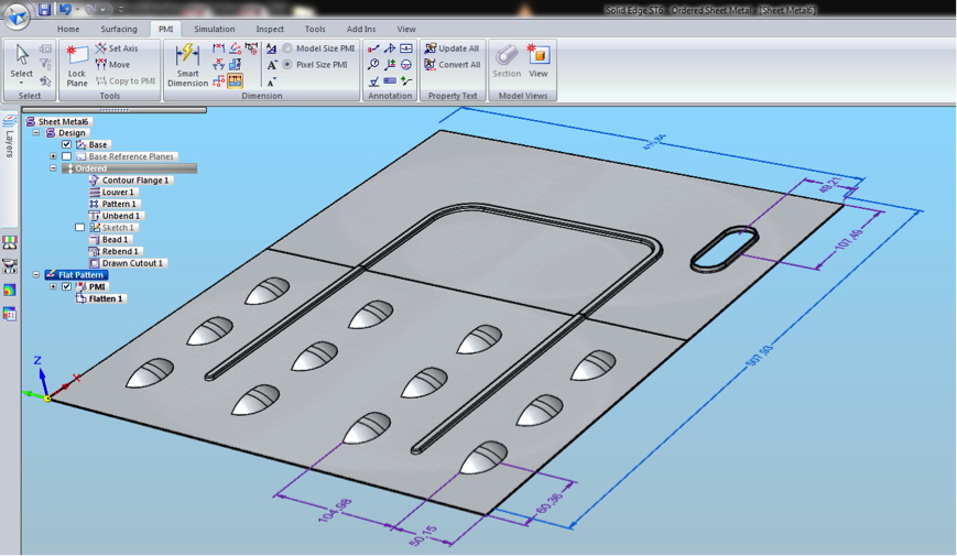
When creating flat patterns in
Solid Edge many options can be preset to speeding up design processes. In the sheet metal model shown in Image A , numerous deformation features including louvers, a drawn cutout,
and a strengthening bead exist. Several options can be preset to either
have these features show as is or as a flattened sheet metal part (Image
B).
 |
| |
| Image A |
 |
| Image B |
Another possibility exists to show where the deformation features are located in the flat but not necessarily show the actual features. Shown in the image below you will notice that the edge lines of the features are shown as well as the X, Y location of the center of the geometry.
Navigate to the Application settings to locate find the options for flat treatments.
Notice other settings for the flattened models such as the options for adding corner breaks either radiuses or chamfers at the exterior or interior corners (Image E). Instead of taking the time to add corner treatments to a design, you have a single setting that will automate this.
 |
| Image E |
For those who require a flat 2D DWG these setting export to the Save As Flat which has its own set of options such as including or excluding layers and exporting back to ACAD 12 DWG.
There is also a hidden gem for flattening an inserted part copy of a sheet metal part. It may be the “old-school” way of flattening a part for post processing, but there are commands that allow the actual flat sheet metal part to have post processing completed (Image G).
Dylan Malek
Application Engineer
Swoosh Technologies


No comments:
Post a Comment