Showing posts with label ST6. Show all posts

Tuesday, July 22, 2014

Imported Sheet Metal Solid in Solid Edge ST6

Solid Edge offers very powerful sheet metal tools. For this blog post, I imported a STEP file that I need to transform to sheet metal and generate a flat view. Upon opening the file, I noticed it was drawn as a solid part and was designed without any radii. With Solid Edge, I have the ability to quickly and easily prep this solid model for its transformation into proper sheet metal model.


To begin, I need create some separation between the two solid corners of the model; this is necessary for Solid Edge to recognize it as flange. In Sheet Metal there is a tool, Rip Corner,   that allows us to quickly add the cuts into the edges creating the needed separation.


Now I utilize Solid Edge’s Transform to Sheet Metal  to convert the solid body into a sheet metal part. During this process I define my Sheet Metal options including the shape and size of the relief cuts, bend radius, and neutral factor (K- Factor). If I chose not to make any changes to the options, Solid Edge will automatically recognize the thickness of the model and apply the default settings in the Material Table (See the video below). Then it’s just a matter of selecting a base face (the main tab of the new sheet metal model) and watch Solid Edge complete the transformation.


Notice the Pathfinder now has new features: a Tab and Flanges 1 thru 5, radii have been added to all the sharp corners, and the previously ripped corners are ready for any corner treatments you wish to add. Please see the video below to see the transformation in real time and watch how I change the corner treatments and make some synchronous changes to the model to generate the flat pattern.


Written by:
Sam Estrada
Application Engineer
Swoosh Technologies


Wednesday, May 28, 2014

How to Use Variable Tables in Solid Edge

Solid Edge has the capability of using a Variable Table to help define and edit functional relationships between variables and dimensions of a design in a familiar spreadsheet format.  This tool can be leveraged to automate your design process. This article gives a basic overview of how the table functions and how to incorporate values from an external spreadsheet to drive a design. If you have a programing background, you can even create your own VB script and take your automation to a whole different level.

Basic Variable Table

Here is a simple design of a block with the some basic dimensions. To begin using the Variable table you must have the dimensions that you wish to control “locked” (They will be displayed as red).


To get to the Variable Table go to the Menu Ribbon and select Tools and then Variables.


In the Variable Table you will see all the data that is associated with the design. In this table you can see the variables and dimensions, names, values, rules, formulas, and other columns. Here we renamed the dimension names from the Solid Edge default of Linear_* to Height, Length, and Width making it easier to identify. Also see the locks allowing you to go in and edit the Formula columns. If these were unlocked this option would not be available.


 Now you can drive the design from here.  By double clicking the Value cell, you can change the dimensions in real time. The Formula column can also be used to add a formula to drive a dimension that in-turn drives the design. This example shows a very simple formula; you can get as complex as you want by adding in your own variables and using them in your formulas. 

If you right click on a value, and select the Variable Rule Editor you can control the values to limit it to a list of specific values or you can set a min/max limit. See the video below.


Excel Spreadsheet

You can also drive a design from an external Excel spreadsheet. Here is another block setup with some locked dimensions and a cutout that is constrained to the center block. A spreadsheet with some dimensional values with driving formulas has also been created.


Inserting the data into Solid Edge is as easy as copy and paste. Once the link is pasted, you can drive the design directly from the spreadsheet (just as above from the variable table). With the spreadsheet, your imagination is the limit. You can utilize all the power of Excel: macros, formulas, and programing. We have customers creating whole product lines from one single spreadsheet. See the video below for an example:


This is just scratching the surface. Using this tool Solid Edge and/or extra options that Excel or Visual Basic offer, you can really accelerate your design.

Looking for training in Solid Edge? Check out the current training schedule or request a class here.

Sam Estrada
Application Engineer
Swoosh Technologies

Tuesday, March 25, 2014

Creating 3D Frames in Solid Edge ST6

Solid Edge speeds design of rigid frame structures beginning with a 3D sketch defining the frame skeleton. Solid Edge automatically creates frame components using standard cross-sections and generates cut lists for manufacturing.

Discover the ease of use when creating 3D frames in Solid Edge using the Frame Wizard. Swoosh Technologies’ Application Engineer, Dylan Malek, walks you through steps to create a frame in Solid Edge. Also, discover new features in the latest version – Solid Edge ST6.

Tuesday, February 25, 2014

Speed Up your Performance with Large Assemblies in Solid Edge

No one likes wasting time waiting for parts and assemblies to open, and once they do open waiting for the software to catch up to rotations, zooms, adding features and parts to assemblies is very frustrating. Let’s go over a few settings that can greatly enhance your performance with large assemblies in Solid Edge.


Shown above are the default settings in Solid Edge for assembly opening. From the opening Solid Edge splash screen follow this path: Application button/Solid Edge Options/Assembly Open As. Set the Open As setting based on your hard ware configuration and personal preference.

For example, you have a really powerful desktop with a huge amount of RAM let’s say around 20 GB, a dual 2 GB video card setup, and a 15,000 RPM SCSI hard drive, “because who wouldn’t want a get up like this”? With a workstation like this you could easily open 2,000 part assemblies with all parts active and all design features turned on, but if you’re like the other 95% percent of us using adequate equipment to get the job done the settings are very important and often ignored or over looked.

 Using the default options, we get an assembly open with all parts, including sub-assembly parts inactive. By inactive I am referring to the parts that are visually seen but not fully loaded into memory thus saving load time. Keep in mind parts that are inactive are not usable until the are activated, which is simply done by right clicking on the part and setting it active.


Another option on the Open As settings panel is to use simplified parts in lieu of designed parts. Shown above you notice what the ‘use simplified design’ will do for you. If the bolt quantity is 200 then you will have 200 complicated helical features that have to be calculated every time you rotate the screen. Helical features are synonymous for being memory hogs, therefore, if the feature doesn’t have any bearing on your design there is no need to have it shown. The time savings gained by taking less than a minute to simplify the design will greatly be compounded in the assemblies the parts are used in.   


For those of you whom prefer to set or change the Open As permitters also have the option to tweak all the individual Open as settings from the open dialog box.

I use this when I open a large assembly that has not had features simplified or if there has not been configurations created that may have time saving benefits such as allowing the user to only open and see the part(s) wanted. I am sure to change the setting to open with all parts turned off. Once I have my empty assembly open, which opens quickly regardless if theres five or 50,000 parts, I begin turning on parts and subassemblies making configurations and simplified parts as I go through the assembly structure. Or if you have the time just say open, go get lunch, maybe a run to the post office, or perhaps wait for the cable installer to show up - it’s really your choice!


Once the assemblies open, there are still many the settings configure. Under the view drop down there are settings for the quality of geometry and the style of viewing such as “Default, High Quality, and Rendering.” There are also settings in “View Overrides” that allow you to turn on reflections, bumb maps, textures, high quality shadows etc. Keep in mind that the more “fancy-flashy” looks take a toll on performance if you don’t have a quality video card to drive them.


Speaking of video cards, there are several selections to choice from based on your video card performance. Shown below are these options. If you uncheck the Automatic selection box, the option to change the settings manually appear. Here is a list of  of the definitions available for selection given by Siemens PLM:
  • Graphics Card Driven (Advanced): This option provides full acceleration for all 3D displays and should provide the smoothest display possible for manipulating graphical objects or editing profiles and sketches. To achieve this higher quality display, Solid Edge requires a higher level of graphics card support. Such support may not exist for older graphics cards. This option is designed specifically for use with the latest mid-range and high-end graphics cards.
  • Graphics Card Driven (Basic): This option provides full acceleration for all 3D displays and should provide a stable display across a wide variety of midrange to high-end graphics cards. While all displays are hardware accelerated, this option avoids accessing graphics requests that may not be widely supported. Choose this option if Solid Edge is unable to generate consistent displays when using the Graphics Card Driven (Advanced) option.
  • Graphics Card Driven (Direct3D): This option is available for the Windows Vista operating system only. This option is intended for Windows Vista users who are unable to generate consistent displays using one of the other graphics card driven options. 
  • Backing Store: This option provides a mixture of graphics card and software generated displays. When you manipulate a view, Solid Edge directs all display requests to the graphics accelerator to provide the fastest frame rate possible. When the view manipulations are completed, the final display is generated using a slower, more stable software method to provide a consistent display for all possible configurations. Choose this option for older, legacy configurations, especially when working with graphics cards that are not designed to support CAD applications (gaming or consumer-level graphics cards), or if Solid Edge is unable to generate consistent displays using one of the graphics card driven options.
  • Software Driven: This option is provided for diagnostic purposes and should not be used for normal displays. The primary reason for this option is to isolate the source of any graphic anomaly that might occur. In most cases, the graphics driver contains a flaw or is out-of-date. This option should only be selected if directed by support to verify such a condition.
  • Use Display Lists: A display list is an OpenGL(r) capability that allows the CAD application to load geometry to the graphics card memory. This off-loads that data from the system memory. Using the dedicated resource on the graphics card is much faster than using shared system memory. This option is set by default for most midrange to high-end cards. A display list increases the performance of the Graphics Card (Advanced) method so that the display rate approaches and sometimes matches the display rate of the Graphics Card (Basic) option.

There is no special combination of settings and configurations that you should set. Every computer is different and some settings do not work great on certain computers. My Dell Laptop doesn’t render correctly when set to Advanced, but works great on Basic. I hope some of these tips help to speed up your performance in Solid Edge!

Dylan Malek
Application Engineer
Swoosh Technologies

View the current Solid Edge training schedule here!


Tuesday, February 11, 2014

Solid Edge How-To: Create Inter-Part Relationships in ST6

In this blog entry, I will answer a question from the last month’s Solid Edge Short covering Assemblies in ST6 (View the webinar replay here). During the webinar, I briefly covered how Inter-Part Relationships are created in Solid Edge ST6 and how a part’s geometry can “drive” another part’s geometry - specifically, how the “rail_side” was driving cylinder placement in the “side plate” part. (Image 1) The question submitted was: “Can this method also drive the size of the cylinders in the “side plate”, and would this method work on if the cylinders were created with the “Hole” command and were threaded?” (Image 2). It is best if I break this question down into two parts. I will begin with the same assembly as before.
Image 1
Image 2
Driving the Size of the Cylinders

1.  Create the necessary assembly relationships between the “rail_side” and the “side plate” part, run the “Create Inter-Part Relationships” command and review the dialog box.

a.  Click on the “Create Inter-Part Relationships” button


b.  Review the dialog box, and note the “Equal Radius” box is checked at the top and the command has recognized the “Equal Radius” in the list.


c.  Click “Save”. Notice in pathfinder, the icon next to the part being driven should change and show two chain links.

2.  Next, “Edit In Place” the driving part in chase the “rail_side” part and create some Face Relate Relationships between the cylinders. This will allow for all cylinder sizes to change at once. 

a.  With “Edit In Place” active, rotate the “rail_side” part around to see the cylinders. Then in the Home Tab, locate the Face Relate section and chose “Equal Radius”. (Note: Have the persist lock active)

b.  Following the directions in the command prompt, have all cylinders equal to the one in top left of the part. (Note: When using face relate commands, the sequence is: select seed face > accept (right mouse click) select target face > accept > accept) 

Make all cylinders equal to this one.
c.  The relationships now appear in the pathfinder.


3.  Go ahead and change the size of the hole cut out (top left corner) and the rest will follow suite. Then “Close and Return” to the assembly and see that the cylinder in the “side plate” will automatically change to the new size.

a.  Changed the hole size from .219” to .3”. As soon as the change is accepted the other cylinder changed as well.


b.  Click on “Close and Return”


c.  Notice the hole cut out change made on the “slide plate”


Threaded Cylinders created with the “Hole” command

When using the Hole command to place cylinders not only are you cutting away material you are creating intelligent procedural features. Therefore, when looking at threaded cylinders, there can be quite of bit extra information added to the cylinder.


The “Create Inter-Part Relationships” only recognizes the part geometry in each part to drive one another. It will not take the extra information added by the Hole command and use it to drive another hole in a separate part in an assembly. There is a way to can obtain the same relationship by using a different assembly command.

1. Inside the assembly environment and under the “Features” tab there is a Hole command used to create a threaded hole.


2. A dialog box will display some different “Assembly Feature Options”. The threaded hole will be an “Assembly-Driven Part feature” and will be driven on the assembly level, but the threaded hole will be placed in each individual part.

a. Select “Assembly-Driven Part feature” and click OK.


b.  Set the Hole options.


c. Place the Threaded Holes on the parts. In this example, I am placing a ¼ inch threaded hole that will go through two blocks.


d.  Next accept the “cut direction”.


e.  Finish out the command. The threaded holes are now placed in both blocks. The pathfinder has a gold chain link indicating that they are both linked and a new entry “Assembly-Driven Part Feature”. Expanding this item will show the entry for the new threaded holes.


3. When the threaded hole size (or any attribute) is changed, the link that was created will make the change in both parts.


I hope these tips will help further your design experience!

Sam Estrada
Application Engineer
Swoosh Technologies

Tuesday, December 17, 2013

Solid Edge How To: Install Multiple Versions of Solid Edge

New with Solid Edge ST6, you can now have multiple versions installed on your workstation. This is useful if you want to do program testing or if you wanted to keep files in an older format. Using multiple versions is not for everyone; Siemens recommends if you are working inside of a production environment, that you only have a single version of the product installed. This is because add-on products like Mold Tooling, SE Teamcenter Client, and Solid Edge SP will not work correctly. Therefore, before you attempt this type of installation please check with your IT department, and read and understand the Solid Edge Installation Guide. This blog post will cover the installation of ST5 and ST6.

NOTE: These instructions are for Windows only.


Let’s get started!
 

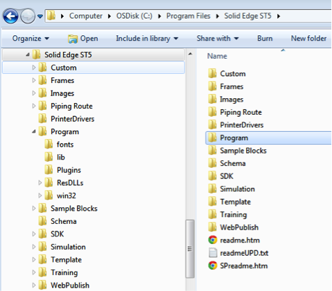
For the multiple version installation to function correctly, you must have either ST5 or ST4 installed on your workstation first before you install ST6. Do not install a different 32/64 bit version of Solid Edge; if you have a 32bit version installed, the newer version must be the same bit version. The older version is a standard installation and should be done as per the Installation Guide.


Have the older version installed first


Once ST5 has been installed, you are ready to install ST6 using the “Silent Installation” method. If you try to install it using the standard installation produces, you will receive an installation error. To begin the process, open up the “Administrator Command Prompt”. To run this go to your start menu, select the “Accessories” folder, locate the “Command Prompt” program, and right-click on the icon. From the drop down menu, select “Run as Administrator”. This will launch the admin command prompt and will ensure you have the necessary rights to proceed with the silent installation.


You will use this window to run the command string that will install ST6 with the correct install parameters. At this point you need to ensure that you have your ST6 installation media loaded or you have it located on your hard drive. Below is the out of the box command sting that will kick off the silent install:

msiexec /i "<drive_letter>or<local_disk_location>:\Solid Edge\Solid Edge ST6.msi" MYTEMPLATE=3 USERFILESPECXML="C:\temp\My Docs\SEAdmin\Options.xml"
USERFILESPEC="C:\License Files\Network\ST6\selicense.dat"
INSTALLDIR="C:\Program Files\Solid Edge ST6" /qn+ /l*v "C:\temp\mysilentsetup.log"

You will need to modify this command before you execute the command. Copy the command text into Notepad (or similar program) and make the necessary changes there. When you are finished, you can copy and paste it into the command prompt.
 

Use these tips to customize this text:
  • <drive_letter>or<local_disk_location> Enter the correct location of the installation media, ie drive letter or if you have the installation files on your hard drive that location. 
  • MYTEMPLATE - is going to set the default templates in ST6, default is “3” 

  • USERFILESPECXML - is used if you have a specific set of Solid Edge custom options you would like to install with the new version; you can point to the “Options.xml” file located on your hard drive. This is optional
  • USERFILESPEC - can point to the license file that will be associated with the version being installed. This is optional, and a license file can added later using the License Manager.
  • INSTALLDIR - is going to set the installation location of ST6, ensure that the install path defined is different from the other version of Solid Edge already existing on your workstation
  • C:\TEMP\MYSILENTSETUP.LOG - will create a log file of the installation in your temp directory.
Here is an example of the command string used on my installation:
msiexec /i "C:\Swoosh Files\Solid Edge ST6 Program\SEST6_64_100\Solid Edge ST6.msi" MYTEMPLATE=4 INSTALLDIR="C:\Solid Edge ST6" /qn+ /l*v "C:\temp\mysilentsetup.log"


Once you have your command string ready, copy it out of Notepad and paste it into the Command Prompt that you have open.

After you execute the command (press enter), there will be no indication that the install is running. The installation will run in the background until complete, in which case it will inform you if it was successful or not.


If there was a failure, you can access the install log file that was created during the install process. Refer to the last line of the command string for the log file location.


When complete, navigate to the install directory and verity that ST6 was installed with all of its components, and if you like, create a shortcut to the EDGE.exe on your desktop.


At this point, if you did not link a license file to ST6, go to your start menu, locate the Solid Edge ST6 folder, Licensing, and run the License Utility to link it to your ST6 license file. 


 Now that you have two Versions of Solid Edge on your workstation, you still need to copy the “Set Active Solid Edge Version” application located on your installation DVD. Explore the DVD and navigate to this folder “<disk_drive>:\Solid Edge\SptTools\SESetActiveVersion” 


Copy this folder to your workstation. Then open the folder and create a shortcut to the “SESetActiveVersion.exe” on your desktop.
                                                              

You will be able to use the “SESetActiveVersion” application to switch between active versions of Solid Edge. To activate a version, select the desired option from the drop down list and click “Activate.” If you do not set the correct version, you may encounter some program errors.


Note: If you need to uninstall Solid Edge from your workstation, it is recommended that you uninstall all versions of Solid Edge and reinstall the production version from scratch. The possibility of corruption of the remaining versions exists following the uninstall of one version of Solid Edge.
 
Good luck and happy designing!

By Sam Estrada, Application Engineer, Swoosh Technologies & Solutions