Showing posts with label Solid Edge. Show all posts

Thursday, October 16, 2014

We Challenge YOU! New GrabCAD Design Challenge

Siemens PLM’s Solid Edge team is sponsoring another great challenge hosted by GrabCAD! This is your chance to trick out the Razor Crazy Cart by Razor USA to showcase your creativity, quality of design and design thinking. Simply download models, start designing, create a render and animation using Solid Edge and KeyShot, and submit it online.

If you are not a current Solid Edge user, start your 45 day trial here for your opportunity to win!

If you currently use Solid Edge, but want to show off your design with KeyShot’s amazing photo-realistic rendering capabilities, start your trial of KeyShot here.


You could win a Microsoft Surface Pro 3, a subscription of Solid Edge Premium with KeyShot Pro and Animation and a Razor Crazy Cart! Click here to view the details and submit your design today!

Wednesday, October 15, 2014

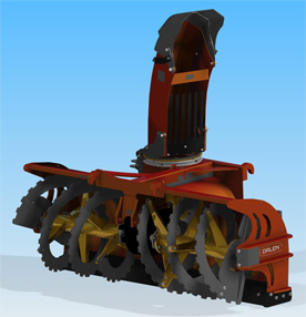
Forestry and agricultural products maker enhances product quality and durability

Lid Jarnindustri designs better with Solid Edge. As a result, the company is now able to compete with low-cost suppliers. It has enhanced customer service, increased speed for altering product design, improved communication between customers, designers and its production line, and reduced the number of physical prototypes.

Learn how here.

Start your 45 day free trial of Solid Edge here.

Wednesday, October 1, 2014

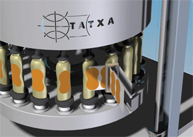
Labeling machine manufacturer optimizes material use, implements near error-free design process

TATXA designs better with Solid Edge. TAXTA specializes in the production of labeling machines for the food, cosmetic and pharmaceutical industries, as well as for cleaning products and other special applications. Other results included reduced costs across operations, increased machine availability and opportunity, and improved product performance as well as product aesthetics.

Learn how here! 

Start you r45 day free trial of Solid Edge here.

Wednesday, September 24, 2014

Hyundai Motor Co. reduces time and cost needed to design car body assembly lines

Hyundai Motors designs better with Solid Edge. The move from 2D to Solid Edge 3D provided a 20 percent design time reduction. Hyundai chose Solid Edge for its ease of use in solid modeling as well as the efficiency of its 2D drafting performance and integrated data management. Solid Edge helped increase quality and reduced repetitive tasks.

"By using Solid Edge to implement 3D CAD with design management, we have been able to effectively reduce design time and costs."

- Jung Hyun Seok, Assistant Manager, Automation Design Team

Learn how here!

Start you 45 day free trial of Solid Edge today here.

Wednesday, September 17, 2014

Agricultural Machinery Manufacturer Reduces Design Time from Three Weeks to Three Days

Harsh International designs better with Solid Edge. Using Solid Edge’s synchronous technology, Harsh also reduced a large project from 18 months to 6 months and developed a prototype of a revolutionary gasification machine. “Solid Edge with synchronous technology is changing our engineering, it’s changing our company and it’s changing our industry,” said Kenny McDaniel, engineering consultant for Harsh.
Learn how here!

Start your 45 day free trial of Solid Edge here.

Tuesday, September 16, 2014

Animating with KeyShot and Solid Edge ST7

Rendering and animating in Solid Edge has never been easier thanks to the complete integration of KeyShot into Solid Edge ST7. Solid Edge has always had descent rendering, but it was graphic card based; however, the application could be slow when rendering especially when animating high end renders which could takes a few days create.

Animating and rendering your CAD models with Solid Edge takes a fraction of the time utilizing a blazing fast CPU rendering engine of KeyShot. Though, using KeyShot alone lacks the finesse of Solid Edge’s animation abilities. Thanks to the integration of the two software applications, designers now have an extremely fast and an easy to animate tool!

Swoosh Technologies’ Application Engineer, Dylan Malek, walks you through creating an animation in utilizing this new integration in Solid Edge ST7 and KeyShot 5. Learn how to create new motors, apply color and textures to renders, and more in the video below.


The final animation:


Learn more about rendering your models in Solid Edge and KeyShot with training from Swoosh Technologies. Contact us today to request a customized course to better visualize your products and increase sales/marketing capabilities.

Wednesday, August 27, 2014

Nucleic acids provider speeds DNA synthesis machine design with more data re-use

Integrated DNA Technologies designs better with Solid Edge. Serving academic, government and commercial researchers in biotechnology, clinical diagnostics and pharmaceutical development, the company also uses Solid Edge and Teamcenter to enhance communication and access to product data company-wide and build new business opportunities.

Learn how here.

Start your 45 day trial of Solid Edge here.

Wednesday, August 20, 2014

Design and manufacturing services company makes CAD changes 10 times faster than traditional history-based CAD

Trlby Innovative designs better with Solid Edge. The use of synchronous technology helps a small company impress its large company customers. Other results from synchronous technology use include easily beating customer deadlines, exceeding customer expectations and creating designs not feasible in history-based CAD. Trlby provides diversified product design, development and manufacturing services for a client base that is almost exclusively made up of Fortune 500 companies across multiple industries.

Learn how here. 

Start a free trial of Solid Edge here.

Wednesday, August 13, 2014

Solid Edge ST7 Assembly Simulation

Siemens has created great software that allows seamless transition of geometry that may have once seemed impossible or very difficult to make useful as well as time consuming. Solid Edge with the latest release of ST7 has the ability to take a single body translated parasolid file and quickly modify it to have multiple bodies.

Application Engineer, Dylan Malek, walks you through the short steps to converts these bodies into sheet metal parts, which then allow to make mid surface faces. These faces can then be easily and accurately used in Finite Element Analysis or FEA.

Splitting the surface to do point load analysis in most FEA software can be very tedious. However, in Solid Edge ST7, the model in the video below took three simple steps for the part to be ready for a load to be applied.

Have questions? Comment below or contact Swoosh Technologies today to learn more.

Wednesday, August 6, 2014

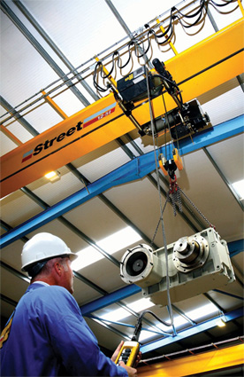
Crane manufacturer gains tight control over millions of product configurations

Street Crane designs better with Solid Edge. With Solid Edge, Street Crane addresses the challenges of complex data management, control and access by Internal and external users.  The results include significantly improved customer response/support, greater product innovation and tight control over millions of possible product configurations.

Learn how here.

Try Solid Edge free here.

Thursday, July 31, 2014

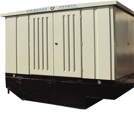
Electrical switch manufacturer meets customers’ design requirements 30% faster

Long-Yuan Switch Equipment designs better with Solid Edge. Advanced sheet metal modeling tools shrink cycle time for electrical equipment by 30 percent. Other benefits delivered by Solid Edge include a 100 percent material use rate and greater agility in addressing domestic and international market trends as well as weathering economic downturns.

Learn how here. 

Start your Solid Edge subscription today and get your first month FREE! Offer ends September 30, 2014.

Tuesday, July 22, 2014

Imported Sheet Metal Solid in Solid Edge ST6

Solid Edge offers very powerful sheet metal tools. For this blog post, I imported a STEP file that I need to transform to sheet metal and generate a flat view. Upon opening the file, I noticed it was drawn as a solid part and was designed without any radii. With Solid Edge, I have the ability to quickly and easily prep this solid model for its transformation into proper sheet metal model.


To begin, I need create some separation between the two solid corners of the model; this is necessary for Solid Edge to recognize it as flange. In Sheet Metal there is a tool, Rip Corner,   that allows us to quickly add the cuts into the edges creating the needed separation.


Now I utilize Solid Edge’s Transform to Sheet Metal  to convert the solid body into a sheet metal part. During this process I define my Sheet Metal options including the shape and size of the relief cuts, bend radius, and neutral factor (K- Factor). If I chose not to make any changes to the options, Solid Edge will automatically recognize the thickness of the model and apply the default settings in the Material Table (See the video below). Then it’s just a matter of selecting a base face (the main tab of the new sheet metal model) and watch Solid Edge complete the transformation.


Notice the Pathfinder now has new features: a Tab and Flanges 1 thru 5, radii have been added to all the sharp corners, and the previously ripped corners are ready for any corner treatments you wish to add. Please see the video below to see the transformation in real time and watch how I change the corner treatments and make some synchronous changes to the model to generate the flat pattern.


Written by:
Sam Estrada
Application Engineer
Swoosh Technologies


Tuesday, July 15, 2014

Solid Edge Assembly Based Features

Solid Edge has the ability to work just like you! For example, there are certain situations where there are machining processes that take place after parts are assembled, I will refer to these as post process features. One reason for the post processes is to make sure everything bolts up after assembling piece parts. While watching the video below you will notice several types of assembly based features, but the ones I focus on are for cutting parts and adding features that will either have welds joining them or features that can be turned into welds. While there are multiple types of assembly features such as rounds, chamfers, holes and protrusions the ability to create your own work flow is based on when and where all these feature are placed.


In the screenshot above, you will notice options for each of these assembly features. The first on the list is Create Assembly Features; this will have your feature only show in the assembly level where it was drawn. The next option is Create Assembly-Driven Features; this will allow the feature to be created in the assembly level, but the actual feature will be shown in the parts that are affected by the feature. The last option is Create Part Features; these features are started at the assembly level but once you finish the feature it will be then moved and controlled at the part level allowing you to cut multiple part files at the same time. Yet each part will have its own feature added to the part pathfinder and not create an assembly feature.

The second type of assembly features Solid Edge offers are weld features. This is perhaps the most used type of post process feature. To create welds in Solid Edge a single button toggle is all that’s needed as shown in the image below. Under the Tools drop down menu select the Weldment configuration, and select the check box for making the assembly a weldment. Once this is done you can now apply weld labels or actual weld beads to help get a more accurate weight on final assemblies.


Written by
Dylan Malek
Applications Engineer
Swoosh Technologies

Learn more about working with assemblies in Solid Edge with training from Swoosh Technologies. Enroll today or request a customized class here.

Wednesday, July 9, 2014

Food processing machine manufacturer reduces design time 45 percent

Eskort Makina  designs better with Solid Edge. Using synchronous technology, new engineers can work on current models and not have to worry about the history of how the design was originally created. Design time was reduced 45 percent and manufacturing costs dropped 20 percent.

Learn more here.

Start your 45 day free trial here.

Wednesday, July 2, 2014

Machine housing maker directly modifies sheet metal design, increases process efficiency

Hatakeyama designs better with Solid Edge. With Solid Edge’s synchronous technology, Hatakeyama  directly modifies geometry and dramatically increasing process efficiency. Other results include near elimination of costly rework and enhanced communication between design and manufacturing groups. 

Learn how here!

Try Solid Edge free here. 

Wednesday, June 25, 2014

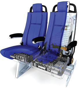
Truck, bus and train seat maker improves design process and ensures customer data compatibility

Freedman Seating designs better with Solid Edge. Moving from SolidWorks to Solid Edge improves the design process while ensuring data compatibility with customers and suppliers. Freedman now has a better ability to meet short lead times as virtual prototyping replaces physical testing. Freedman achieves more design re-use with part count down by 50 percent.

Learn more here!

Start your 45 day free trial of Solid Edge here.

Tuesday, June 17, 2014

Have a Draft and missing your original model? No problem with Solid Edge!

In Solid Edge, the draft file does not need the original model it was based off in order to open and display its information and views. So if you ever find yourself in the position where you have lost your model and all you have left is your draft, not all is lost! You can still use that information to regenerate your 3D model.

Prepping your orphan draft file
When opening the draft file disregard the dialog box about it not being able to find the model.


The off color center line surrounding all the views, is just a visual indicator that the model is missing and nothing will happen if you update the views. You can still add and remove dimensions from each of the views.


All of the information that makes up the view is still there, but you will not be able to select any lines or circles. Think of it as a ghost image. If you try to use the Create 3D command now you will only recognize the dimensions on the draft. You first need to save the draft file as a *DWG and reopen it inside Solid Edge.           


Create your 3D model
With the DWG loaded, clean up the views by removing any extra hidden and center lines, crosshatching, section view text, and border items that might get in the way of the Create 3D command. You can double views to activate the block (if present) and do your deleting there, and afterwards, you will need to “Unblock” the views. (Again if present, performing this step will allow you to select the individual lines.)


Run the Create 3D command, select your *.par template, set your views, and the PAR file will be loaded. You may need line up your sketches to make it easier to create your model, but once there just use your steering wheel to re-create your part.


Watch the video below for more details!


Sam Estrada
Application Engineer
Swoosh Technologies

Thursday, June 5, 2014

Adding Rule Based Dimension and Sensors in Solid Edge

Adding Rule Based Dimension and Sensors in Solid Edge

For those designers who know exactly what the final product is going to be, these couple of Solid Edge features may not help, but those other 99% of us may need some help building intelligence into our design to facilitate future changes.

The first thing to take a look at is Rule Based Dimensions. For example, my company designs skid mounted pressure equipment. Typically these designs have a build envelope to work in. Solid Edge is a great tool to make fast changes, but what if those changes invalidate the design, and you’re not aware this happened? Here’s the formula for this D = Design,  $ + dollars and : ( = wrong change so   D + : ( = $$$$$$$.

You get the idea: a wrong design change typically cost lots of monies and upset bosses. SO the first thing I would do as a designer is add a Variable dimension for a rule based less than or equal to dimension to make sure my overall build stays within my envelope (Read this past post about variable tables in Solid Edge). And to add another level of control to my design we can use Sensors. Sensors allow a designer to add design intent to a model.

As in the case above, we have a skid and we have a sheet metal control box that houses all the electronics. First thing we may need is a lock on the cover. You usually have a hole in the face to allow the locking mechanism to mount to. What happens if a design change came along and said the box need to be narrower, causing the hole the lock fits into gets too close to the edge? When the part is made the guy punches the hole and deforms the sheet metal or even worse it tears along the closest edge. With a few clicks these things can be all be elevated. A simple cutout to edge Sensor can be applied so these things will pop up a warning on the screen notifying you of such conditions.

To wrap this up the old adage fits well (an ounce of prevention is worth a pound of cure).  Swap cure for a wad of money, and our bosses love to hear about all the money you saved the company.

Watch this video to learn how to add rule based dimensions and sensors in Solid Edge:


Dylan Malek
Application Engineer
Swoosh Technologies

Wednesday, June 4, 2014

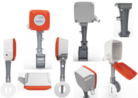
Steam accessories and control instrument maker increases design efficiency 65%

Forbes Marshall designs better with Solid Edge. Move from 2D to 3D allows company to concentrate on innovative new design work. With Solid Edge’s synchronous technology, Forbes also eliminated vendor mistakes due to drawing management issues, saved 150,000 rupees per month and increased its market share.

Learn how here!

Start your free trial of Solid Edge here.

Thursday, May 29, 2014

Solid Edge ST7 packed with Hundreds of Customer Requested Enhancements

Solid Edge University 2014, held during the week of May 12th in Atlanta, brought the launch of Solid Edge ST7. The most powerful Solid Edge yet is updated with hundreds of enhancements requested from you, the user, that allow you to accelerate your 3D modeling, streamline your design management, power up with new apps, and enjoy a user friendly experience.

Solid Edge has always lent its hand to aiding users to design faster and ST7 is no different. 3D Sketch, available in the part, assembly and sheet metal environment, speeds up modeling by rapidly defining 3D paths for sweep operations. 3D Sketch also allows you to model pipes and wires that are bent in more than one plane, and in the assembly environ¬ment for the definition of exact paths for piping, wiring and tubing.


Solid Edge ST7 speeds up the modeling of massive assemblies. Design faster and more flexibly by duplicating components or patterning components along a curve. Performance is faster in massive assemblies and now gives users the control over the extent to which the assembly is recomputed during open and save operations.


ST7 users now have the ability to create photorealistic renderings with integration of KeyShot. KeyShot is the easiest and fastest rendering software that allows users to produce beautiful product images and processes concurrently with modeling operations.  Any changes to the model are automatically updated in the rendered image using the “Live Link” capability with no need for you to reassign materials, set up animations again or update any other settings.

Solid Edge SP, a SharePoint based data management solution received a facelift in the latest release. Visualizing data and assemblies has never been easier. Quickly create workflows for task completion and show multiple property cards at once.

    
Solid Edge is part of a growing ecosystem of apps designed to increase productivity, manufacturing, and collaboration capabilities. These apps allow for mobile access to standard and catalog parts, automated output of models for 3D printing, expanded manufacturing abilities, cloud-based collaboration, and more. This includes CAMWorks for Solid Edge and CADENAS PartSolutions. View the apps available here.

Solid Edge ST7 brings a more intuitive user interface resulting in a faster learning curve and improved efficiency. A visual startup page provides easier access to templates, recent documents, instructional videos, the online community and standard parts. Learning paths that meet the needs of specific users are easier to access, and an improved 3D orientation “quick view cube” enables you to quickly understand model orientation and jump to common views.

Look for our What’s New in Solid Edge ST7 webinar coming soon!

Start your free trial of Solid Edge here.

Candis Spraul
PLM Marketing Specialist
Swoosh Technologies