NX Reuse Libraries aid in assembly with jigs and fixtures by simply dragging the files into the manufacturing setup files. Sample Reuse Library files can be downloaded from Siemens PLM here; however, a webkey is necessary.
Follow these steps to setup a reuse library and create a reuse folder on your computer:
Start NX. This example uses NX 8.5.
Edit your customer defaults by navigating to File > Utilities > Customer Defaults.
A reuse library can be set up at the site level or the users level.
Next, map your new Reuse Library location. In the native NX area dialog box, add the path highlighted below.
NOTE: You may enter any path you wish after the | symbol.
Reuse Examples|$UGII_BASE_DIR/nxparts/Reuse Library/Reuse Examples
Reuse Examples|C:\Users\brian\Desktop\NX85_Reuse\CAM_Reuse_Library_Samples
Select OK to save your defaults.
Exit NX.
Restart NX.
Your new Reuse Library should be now be displayed.
You are ready to create a model in your Reuse Library!
The model you create must reference the column heading in Excel.
Create a new file. Prior to creating any geometry, set up expressions for the column heading. Then create geometry referencing those expressions.
Save your file.
Enter the Reuse Library to view the model.
Learn more about NX Reuse Library and the Manufacturing Resource Library (MRL) through training with Swoosh Technologies. Register for a class or request a customized class here.
Written by
Brian Brown
Application Engineer
Swoosh Technologies
Showing posts with label NX CAD. Show all posts
Tuesday, July 29, 2014
Thursday, July 3, 2014
How to Change the Units of an NX Part File
NX part files are defined with a basal unit of either inches or millimeters, which cannot be changed interactively within NX. This article discusses options that involve unit definitions, conversion, and how units can be managed.
Methods of Managing NX Units
Units Definition
NX provides two default unit system files: one English and one metric. You can choose one of these unit systems when you create a new part file. The settings for that unit system are then applied and stored with the file. By default, all parameters, values, dimensions, expressions, etc. will be created in the same generic system of measurement.
Note: NX does not allow the changing of the unit systems interactively within NX nor does it allow importing a part file of differing unit.
Converting Part File Units
Unit conversion refers to the actual conversion of a part from inches to millimeters, or vice versa. Unit conversion is a stand-alone external Open C and C++ API Program.
The program converts all model data appropriately and applies a conversion factor to all dimensional data (i.e., lengths, coordinates, origins, etc.). Non-dimensional data, such as angles, scalars, etc., are not affected. Therefore, the model maintains the same physical size after conversion.
The program changes the internal representation of the part by:
Built-in (system) expressions are not affected such as “pi”, conversion factors, algebraic and logarithmic functions, etc.
Note: The behavior described below only applies to expressions created in NX 2 or older versions, as well as expressions created in NX 3 or newer versions, which have a dimensionality of Constant. That is, there are no units assigned to the expression.
Example of using ug_convert_part.exe :
Note that the default directory where the command line starts is in the folder of the username “garrett” on the computer. Therefore, in order for the operating system to find the actual command file, the pathname of the containing folder, C:\Siemens\NX8.5\ugii\, also needs to be entered in front of the command. This is the “root directory” of NX. There are other methods of running this executable.
Before:
After:
The Units Manager
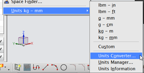
The Units Manager allows you make changes to units of measure and create new unit systems. Create a custom unit when you want to use a unit other than the available five standard units. New information from each Units Manager session dynamically updates in all key dialogs. To do this navigate to Analysis > Units > Units Manager.
This tool should only be used in a controlled environment where all users accessing the data understand the practice and application of the managed units.
Built-in Conversion Functions
NX expressions allow you to convert values as you enter them in value fields as shown below.
It is often necessary to enter values into text entry fields that are based on another unit system than that of the Work Part such as creating a clearance hole in an inch part file to accommodate a metric fastener. The value of the hole diameter can be entered as the metric diameter converted to inches in an expression.
NX Help lists all of the built-in conversion functions as follows:
Units Converter
Instead of using a conversion function, a simple unit converter command can be executed during a command. This gives the user the value desired for the text entry field of the feature. It is a simple “constant” value for the parameter of the feature. To do this navigate to Analysis > Units > Units Converter.
Simply enter the value you have in the “From” field and select the units of the value. The “To” field immediately reports the converted value in whatever unit is selected.
Changing the Analysis Units Option
Performing a distance measurement results in a linear value in the same units as the part file by default. At any time, the analysis (measurement) units can be changed to whatever unit system is desired by executing a Simple Distance Measurement command (see below).
Then select two objects in the graphics area. A ruler and a value box appear with the value in part file units.
Follow these steps to change the units:
1. Choose Analysis->Units.
2. Change the units from inches to millimeters.
3. Measure the length again and the popup will be in millimeters.
4. Measure the diameter of a hole… also millimeters.
Stop now and consider the ramifications…
Changing the units in the Analysis drop down has a tremendous impact on subsequent modeling functions!
Changing the Analysis Units –CHANGES THE MODELING UNITS!
Before:
After:
It should be understood that this modification of the analysis units is NOT changing the unit system of the part file, only the units in which all expressions are being created. And, as you can see above, none of the existing expressions are affected.
Default Behavior in Other Applications
NX Assemblies are able to contain components of mixed units without lack of functionality with the exception of Working In Context – the Work Part cannot be a Component file with different units from the Displayed Assembly.
Regardless of the units of the Master Model, the Drafting Application is able to allow either inches or millimeters for:
Summary
This article discussed options that involve unit definitions, conversion, and how units can be managed.
In an engineering/manufacturing environment where unit definition is mixed, robust solutions are available. With the various methods offered by NX, however, the user must be careful and think of downstream applications that may be affected. Also, corporate standards should dictate how these methods are to be implemented to avoid confusion and errors.
Written by:
Garrett Koch
Application Engineer
Swoosh Technologies
Methods of Managing NX Units
Units Definition
NX provides two default unit system files: one English and one metric. You can choose one of these unit systems when you create a new part file. The settings for that unit system are then applied and stored with the file. By default, all parameters, values, dimensions, expressions, etc. will be created in the same generic system of measurement.
Note: NX does not allow the changing of the unit systems interactively within NX nor does it allow importing a part file of differing unit.
Converting Part File Units
Unit conversion refers to the actual conversion of a part from inches to millimeters, or vice versa. Unit conversion is a stand-alone external Open C and C++ API Program.
The program converts all model data appropriately and applies a conversion factor to all dimensional data (i.e., lengths, coordinates, origins, etc.). Non-dimensional data, such as angles, scalars, etc., are not affected. Therefore, the model maintains the same physical size after conversion.
The program changes the internal representation of the part by:
- Converting internal values as necessary
- Converting expressions
- Maintaining display values (drawings and dimensions still display in their creation units)
Built-in (system) expressions are not affected such as “pi”, conversion factors, algebraic and logarithmic functions, etc.
Note: The behavior described below only applies to expressions created in NX 2 or older versions, as well as expressions created in NX 3 or newer versions, which have a dimensionality of Constant. That is, there are no units assigned to the expression.
Example of using ug_convert_part.exe :
Note that the default directory where the command line starts is in the folder of the username “garrett” on the computer. Therefore, in order for the operating system to find the actual command file, the pathname of the containing folder, C:\Siemens\NX8.5\ugii\, also needs to be entered in front of the command. This is the “root directory” of NX. There are other methods of running this executable.
Results of Conversion
Before:
After:
The Units Manager
The Units Manager allows you make changes to units of measure and create new unit systems. Create a custom unit when you want to use a unit other than the available five standard units. New information from each Units Manager session dynamically updates in all key dialogs. To do this navigate to Analysis > Units > Units Manager.
This tool should only be used in a controlled environment where all users accessing the data understand the practice and application of the managed units.
Built-in Conversion Functions
NX expressions allow you to convert values as you enter them in value fields as shown below.
NX Help lists all of the built-in conversion functions as follows:
| Function | Description |
|---|---|
| cm | cm(x) converts x from centimeters into the default units of the part file. |
| ft | ft(x) converts x from feet into the default units of the part file. |
| grd | grd(x) converts x from gradients to degrees. |
| in | in(x) converts x from inches into the default units of the part file. |
| km | km(x) converts x from kilometers into the default units of the part file. |
| mc | mc(x) converts x from microns into the default units of the part file. |
| minute | minute(x) converts x from minutes into degrees. |
| ml | ml(x) converts x from mils into the default units of the part file. |
| mm | mm(x) converts x from millimeters into the default units of the part file. |
| mtr | mtr(x) converts x from meters into the default units of the part file. |
| sec | sec(x) converts x from seconds into degrees. |
| yd | yd(x) converts x from yards into the default units of the part file. |
Units Converter
Instead of using a conversion function, a simple unit converter command can be executed during a command. This gives the user the value desired for the text entry field of the feature. It is a simple “constant” value for the parameter of the feature. To do this navigate to Analysis > Units > Units Converter.
Simply enter the value you have in the “From” field and select the units of the value. The “To” field immediately reports the converted value in whatever unit is selected.
Changing the Analysis Units Option
Performing a distance measurement results in a linear value in the same units as the part file by default. At any time, the analysis (measurement) units can be changed to whatever unit system is desired by executing a Simple Distance Measurement command (see below).
Then select two objects in the graphics area. A ruler and a value box appear with the value in part file units.
- For an inch part, the default will be lbm – in.
- For a metric part file, the default will be kg – mm.
Follow these steps to change the units:
1. Choose Analysis->Units.
2. Change the units from inches to millimeters.
3. Measure the length again and the popup will be in millimeters.
4. Measure the diameter of a hole… also millimeters.
Stop now and consider the ramifications…
Changing the units in the Analysis drop down has a tremendous impact on subsequent modeling functions!
Changing the Analysis Units –CHANGES THE MODELING UNITS!
Before:
After:
It should be understood that this modification of the analysis units is NOT changing the unit system of the part file, only the units in which all expressions are being created. And, as you can see above, none of the existing expressions are affected.
Default Behavior in Other Applications
NX Assemblies are able to contain components of mixed units without lack of functionality with the exception of Working In Context – the Work Part cannot be a Component file with different units from the Displayed Assembly.
Regardless of the units of the Master Model, the Drafting Application is able to allow either inches or millimeters for:
- The Drawing file
- Drawing Sheet sizes (“A0, A1, A2” etc. vs “A, B, J,” etc.)
- Drawing and View Scales
- Dimensions (can be either or Dual Dimensioning)
Summary
This article discussed options that involve unit definitions, conversion, and how units can be managed.
In an engineering/manufacturing environment where unit definition is mixed, robust solutions are available. With the various methods offered by NX, however, the user must be careful and think of downstream applications that may be affected. Also, corporate standards should dictate how these methods are to be implemented to avoid confusion and errors.
Written by:
Garrett Koch
Application Engineer
Swoosh Technologies
Labels:
Garrett Koch,
NX,
NX CAD
Location:
St. Louis, MO, USA
Tuesday, June 24, 2014
Creating Macros for Customization in NX
The simplest way to customize NX is through the use of macros
A macro records a series of keystrokes in order to automate them into a simple keystroke or an icon on a custom Toolbar. Any series of keystroke a NX operator does repeatedly should be considered for a macro in order to speed up the process.
Follow these steps to create a macro:
Note: Macros have to be updated between releases.
Macros can be setup for user interaction also and can be paused to give the user instructions. Macros can be setup with user entry boxes or file selection dialog boxes.
Watch the video below to view a macro I created to change the color to green and my translucency to 75%. The video shows how I created the macro and un-did the macro’s result. The video also shows the playback of the macro created for testing.
Brian Brown
Application Engineer
Swoosh Technologies
A macro records a series of keystrokes in order to automate them into a simple keystroke or an icon on a custom Toolbar. Any series of keystroke a NX operator does repeatedly should be considered for a macro in order to speed up the process.
Follow these steps to create a macro:
- Select the tools drop down menu
- Select macro
- Select start record
Note: Macros have to be updated between releases.
Macros can be setup for user interaction also and can be paused to give the user instructions. Macros can be setup with user entry boxes or file selection dialog boxes.
Watch the video below to view a macro I created to change the color to green and my translucency to 75%. The video shows how I created the macro and un-did the macro’s result. The video also shows the playback of the macro created for testing.
Brian Brown
Application Engineer
Swoosh Technologies
Labels:
Brian Brown,
NX,
NX CAD
Location:
Harrisburg, PA, USA
Subscribe to:
Posts (Atom)