Showing posts with label Unigraphics. Show all posts

Thursday, February 20, 2014

6 Reasons Why Manufacturing Companies Train Their Employees

  1. Training improves employee performance. According to Ferdinand Fournies (author of ‘Why Employees Don’t Do What They’re Supposed To Do’) performance problems occur because employees (1) don’t know what they’re supposed to do, (2) don’t know how to do it, and/or (3) don’t know why they should do it. 
  2. Training enhances company profits. Based on the training investments of 575 companies during a three-year period, researchers found that firms investing the most in training yielded a 36.9 percent total shareholder return as compared with a 25.5 percent weighted return for the S&P 500 index for the same period. That's a return 45 percent higher than the market average.
  3. Training saves labor. Reducing duplication of effort, time spent on problem solving, and time spent on correcting mistakes.
  4. Training improves a company's competitive edge. Any company has to recognize that not only is the human capital of their employees a major asset, it is also a depreciating asset that needs continuing investment." Keeping worker skills up to date keeps a company in the running.
  5. Training saves supervisory and administrative time and costs. The less time a manager has to spend on monitoring and guiding employees, the more time is freed up for more profitable activities.
  6. Training improves employee satisfaction and retention. Companies that fail to train their employees are more than three times as likely to lose them.
Swoosh Technologies Education Services has been delivering training solutions for 9 plus years focusing on Siemens PLM Software: NX (Unigraphics), Solid Edge, and Teamcenter.  Ours is not the broad-based training approach which adds little to process efficiencies.  Rather, we focus on industry process training and address your specific areas for measurable results.  Contact us today and we will explore how our training can help your team improve to a new level of achievement.

Click here to view the training schedule and register for a class.

Dan Wibbenmeyer
Swoosh Technologies

Tuesday, February 4, 2014

The Cue Line in NX CAD

“Awww, this must be a bug!”

That’s often the response when an NX user gets hung up during a particular command that has multiple steps or many options. They’re missing that one little tip to help them along in the process. Like the neighbor who borrowed a chainsaw and quickly returned it, claiming it was far too slower than his axe, there was something he didn’t know… I told him, “Well, when you pull this rope it starts the motor.” (Vrooom vroom, VROOOOOOM!) “WHAT’S THAT NOISE!!!???” shouted the startled neighbor!

Sometimes it just takes a small suggestion or a little hint to get past the problem. Such is the purpose of the Cue Line on the NX window.


The Cue Line sits inobtrusively below the Menu Bar, below all those magnificent icons and toolbars, humbly offering words of advice to wayward CAD gurus and neophytes alike. For anyone with even a few hours of pioneering through an NX session, many of the prompts become mundane and easy to ignore. False confidence soon comes and eventually, the Cue Line takes a back seat to nearly everything else on the screen. Users are content to discern their next moves merely by on screen feedback and their own veteran senses. But alas, once the going gets tough, users are sometimes too quick to resolve an insufficiency in software effectiveness instead of their own ignorance.

For instance, here in the drafting function of Broken View, while we try to define the spacing between sections it might be assumed that simply selecting a section and entering a Distance value should be enough. Instead, NX prompts the user to identify from  what we want to space our section from… one of the other reference boundaries.


NX is actually offering a bit more of an option than might be inferred at first. What says the spacing value has to be defined from the section adjacent to it? You can enter a value that determines the section’s location relative to the section of the extreme right end if preferred.

Likewise, by merely selecting the Positioning Method of “Distance” instead of “Inferred”,  NX immediately prompts for a vector object selection. We might have assumed the only direction for a distance would be measured horizontally between the sections since it’s common in this traditional view modification practice.


Another good example is in the creation of a Studio Spline. While defining the points the Cue Line offers suggestions for much more than just “select points to define spline”.


Sometimes we miss out on some really nice options built into the creation process that are often thought of as editing commands.

Sketching also presents some nifty and often unsuspected options. In the example below, we’ve completed some sketch curves and are at rest with no active command at present.


What’s that? “…or double-click an object”? Wha? What’s that about? Double clicking the line on the left side of this rectangle yields a dialog titled “Line (Non-Associative)”. Non-associative? How could a sketch curve that’s constrained to be coincident at both its end points be non-associative? This is a temporary status while in this edit mode whereby we can redefine this line in lieu of existing constraints. Read the Cue Line.


The Cue Line indicates that we can redefine this line by selecting a different end point, even though there is already a coincident constraint at its end point. Selecting on the midpoint of the upper line of the rectangle will yield an interesting result!


The line end point immediately moves to the midpoint of the upper line, as intended, but yet the coincident constraint symbol is still showing up on the end point of that upper line. What will happen to that coincident constraint, we wonder? Choosing “OK”  the dialog yields the result…

We have just moved not only the endpoint of the left line to the selected location but the coincident constraint was also reapplied from the upper line’s endpoint to… well, the upper line’s NEW endpoint – its old midpoint! The Cue Line often suggests creation and editing options we had not thought available.

Avoid the hurdles

One last example: When creating a Through Curves feature, the selection process of the individual section strings can be a little challenging. Firstly, in order to end the selection of the first string and begin the selection of the next one, that’s easily accommodated with the “Add New Set” icon in the dialog. NX will highlight that icon in green, mapping its selection to the middle mouse button. But the Cue Line also reminds us of that in addition to the fact that we can select a mix ‘n match of curves or edges as section objects.

If you’ve ever tried to create a Through Curves feature by selecting all of your intended curves in the first string, you’ll know it complains about curves in the string being disjoint or lacking continuity because they aren’t connected.

When working in Education Services at Siemens PLM Software for nearly 14 years, it was a common joke to state that amongst any 10 instructors, you could 11 different opinions! However, one of the things that all of us agreed on was that the Cue Line was the most important thing on the window. That question was a part of the Designer and Drafting Certification tests. It’s THAT important!


Garrett Koch
Application Engineer
Swoosh Technologies

Thursday, December 12, 2013

Reengineering Model Data in NX

Reengineering describes the process of creating a newly engineered design from a previously complete design, or to “engineer again”, as Merriam-Webster states. However, in the CAD/CAE environment the task can be much more complex than simply developing a product design from scratch as a -1 revision. The capture of physical geometry for shape, size, and location is accomplished by many different processes, machines, and software applications.

There are three general sources from which we create model geometry in a CAD software product:

  1. From a concept in our minds,
  2. From an existing printed drawing,
  3. From analysis and measurement of an existing product, perhaps that of a competitor in our industry.
The latter method involves the practice of reengineering and is growing in business processes and expanding into a diversity of machine technology, computer software, and industry standards. Machines designed to “feel” the features and characteristics of a part have been in a process of refinement for decades. The Coordinate Measuring Machine (CMM) has been developing more accurate and robust output since its inception in the 1950’s. New file formats came into play as each manufacturer and data collection and reduction system improved the assessment and probing technology. And thus, we arrive at the focus of the reengineering effort – reusing this data.

Traditional CMM technology using touch or scanning probes is often combined with other measurement technology today. This includes laser, video, or white light sensors to provide what is known as multi-sensor measurement. Primarily, scanning output is in one of two major formats: point data and polygon data but the file format can come out as:

  • IGES, 
  • DXF, 
  • ASCII, 
  • .stl, 
  • Steinbichler, 
  • VRML, 
  • or others.
Siemens NX (formerly Unigraphics) software is able to utilize both point and polygon scan data types and the different file formats, bringing them directly into an NX part file.

1. Point data from a “.pts” file


2. Polygon data from an “.stl” file


In these two approaches to reengineering the geometry, NX offers tools to accommodate ease of use and accuracy. For point data, the user can create a new part file and choose the Points From File command under the File drop down of the Menu Bar. 


For polygon data, 3D printer format (also known as stereo lithography or “.stl”), or facet body, the user can either open the foreign file format directly with the File->Open command or they can import the data into an existing NX part file


USING POINT DATA

Traditional Surfacing Commands

Since the early days of Unigraphics, there have been commands to accommodate the creation of surfaces by defining either point locations or pole locations. Both commands (from the Insert->Surface Menu Bar drop down) provide a means of importing and creating in one step using a “Points from File” option. Additionally, each method also allows the individual selection of points in rows.


Fit Surface Command

Once the point data resides in the NX part file, various methods are used to use this data in creating surface and solid bodies. A highly efficient command called Fit Surface (new in NX8.5) allows the user to generate a single surface from all or a portion of the points in one step. The points must first be grouped into a set using the command Format->Group->New Group.
The drop down option at the top of the dialog offers analytic as well as freeform options.
 
The process involves the selection of points, a Fit Direction options selection, and an optional step for defining a 4-sided boundary. The level of Parameterization is accommodated with the selection of degree and patches in both the U and V directions of the intended surface. The Smoothing Factor is an approximation control which allows greater or lesser deviation from the actual point locations with the resulting surface having less radical changes in curvature and contour. 


The results of these commands yield patches of the surfacing that can then be trimmed and sewn or combined with other commands like Face Blend, Bridge, Section, etc. Once adapted and manicured to completely enclose a volume, the sew operation will transform the surfaces into a single solid body.

Using Curve Construction Tools
 
Another approach to using the point data, again more traditional, is to create curves (lines, arcs, conics, and splines) from the points near the edges of the intended surface or solid geometry boundaries and then create the surface (sheet) or solid bodies from the curves. The full suite of Freeform tools in NX provides nearly endless solutions to accommodate this approach including: 

  • Ruled, 
  • Through Curves, 
  • Through Curve Mesh, 
  • N-sided, 
  • Sweep Along Guide, 
  • Swept, 
  • Variational Sweep, 
  • etc.

USING POLYGON DATA

Rapid Surface Technology
 

A newer approach that utilizes the polygon (facet or .stl) types of data allows the user to break down the polygon surface areas into general shapes, ideally somewhat analytical in nature but freeform contours are completely acceptable.

 Rapid Surface Creation Process

Creation of Individual Sheet Edges
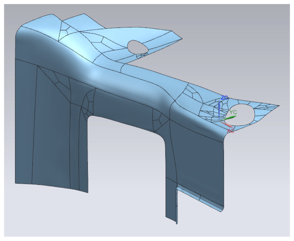
Resulting Surfacing in Sheet Bodies


This process is clearly shown, along with other forms of adapting and using facet geometry in the following video.


SUMMARY

 
Reengineering can be accomplished in many ways and the results are, like many other tasks, always a result of the source data and techniques used. From the techniques shown above, users are able to generate newly engineered parts that can serve as the base model for additional parametric features or can be modified with Synchronous Technology. Hopefully this report provides insight into the many methods that NX can be applied to reengineer existing products.

By Garrett Koch, Application Engineer, Swoosh Technologies & Solutions