Thursday, July 31, 2014

Electrical switch manufacturer meets customers’ design requirements 30% faster

Long-Yuan Switch Equipment designs better with Solid Edge. Advanced sheet metal modeling tools shrink cycle time for electrical equipment by 30 percent. Other benefits delivered by Solid Edge include a 100 percent material use rate and greater agility in addressing domestic and international market trends as well as weathering economic downturns.

Learn how here. 

Start your Solid Edge subscription today and get your first month FREE! Offer ends September 30, 2014.

Tuesday, July 29, 2014

Creating a Reuse Library in NX 8.5

NX Reuse Libraries aid in assembly with jigs and fixtures by simply dragging the files into the manufacturing setup files. Sample Reuse Library files can be downloaded from Siemens PLM here; however, a webkey is necessary.

Follow these steps to setup a reuse library and create a reuse folder on your computer:

Start NX. This example uses NX 8.5.

Edit your customer defaults by navigating to File > Utilities > Customer Defaults.


A reuse library can be set up at the site level or the users level.


Next, map your new Reuse Library location. In the native NX area dialog box, add the path highlighted below.

NOTE: You may enter any path you wish after the | symbol.

Reuse Examples|$UGII_BASE_DIR/nxparts/Reuse Library/Reuse Examples
Reuse Examples|C:\Users\brian\Desktop\NX85_Reuse\CAM_Reuse_Library_Samples 


Select OK to save your defaults.

Exit NX.

Restart NX.

Your new Reuse Library should be now be displayed.


You are ready to create a model in your Reuse Library!

The model you create must reference the column heading in Excel.

Create a new file. Prior to creating any geometry, set up expressions for the column heading. Then create geometry referencing those expressions.

Save your file.

Enter the Reuse Library to view the model.


Learn more about NX Reuse Library and the Manufacturing Resource Library (MRL) through training with Swoosh Technologies. Register for a class or request a customized class here.

Written by
Brian Brown
Application Engineer
Swoosh Technologies

Tuesday, July 22, 2014

Imported Sheet Metal Solid in Solid Edge ST6

Solid Edge offers very powerful sheet metal tools. For this blog post, I imported a STEP file that I need to transform to sheet metal and generate a flat view. Upon opening the file, I noticed it was drawn as a solid part and was designed without any radii. With Solid Edge, I have the ability to quickly and easily prep this solid model for its transformation into proper sheet metal model.


To begin, I need create some separation between the two solid corners of the model; this is necessary for Solid Edge to recognize it as flange. In Sheet Metal there is a tool, Rip Corner,   that allows us to quickly add the cuts into the edges creating the needed separation.


Now I utilize Solid Edge’s Transform to Sheet Metal  to convert the solid body into a sheet metal part. During this process I define my Sheet Metal options including the shape and size of the relief cuts, bend radius, and neutral factor (K- Factor). If I chose not to make any changes to the options, Solid Edge will automatically recognize the thickness of the model and apply the default settings in the Material Table (See the video below). Then it’s just a matter of selecting a base face (the main tab of the new sheet metal model) and watch Solid Edge complete the transformation.


Notice the Pathfinder now has new features: a Tab and Flanges 1 thru 5, radii have been added to all the sharp corners, and the previously ripped corners are ready for any corner treatments you wish to add. Please see the video below to see the transformation in real time and watch how I change the corner treatments and make some synchronous changes to the model to generate the flat pattern.


Written by:
Sam Estrada
Application Engineer
Swoosh Technologies


Tuesday, July 15, 2014

Solid Edge Assembly Based Features

Solid Edge has the ability to work just like you! For example, there are certain situations where there are machining processes that take place after parts are assembled, I will refer to these as post process features. One reason for the post processes is to make sure everything bolts up after assembling piece parts. While watching the video below you will notice several types of assembly based features, but the ones I focus on are for cutting parts and adding features that will either have welds joining them or features that can be turned into welds. While there are multiple types of assembly features such as rounds, chamfers, holes and protrusions the ability to create your own work flow is based on when and where all these feature are placed.


In the screenshot above, you will notice options for each of these assembly features. The first on the list is Create Assembly Features; this will have your feature only show in the assembly level where it was drawn. The next option is Create Assembly-Driven Features; this will allow the feature to be created in the assembly level, but the actual feature will be shown in the parts that are affected by the feature. The last option is Create Part Features; these features are started at the assembly level but once you finish the feature it will be then moved and controlled at the part level allowing you to cut multiple part files at the same time. Yet each part will have its own feature added to the part pathfinder and not create an assembly feature.

The second type of assembly features Solid Edge offers are weld features. This is perhaps the most used type of post process feature. To create welds in Solid Edge a single button toggle is all that’s needed as shown in the image below. Under the Tools drop down menu select the Weldment configuration, and select the check box for making the assembly a weldment. Once this is done you can now apply weld labels or actual weld beads to help get a more accurate weight on final assemblies.


Written by
Dylan Malek
Applications Engineer
Swoosh Technologies

Learn more about working with assemblies in Solid Edge with training from Swoosh Technologies. Enroll today or request a customized class here.

Wednesday, July 9, 2014

Offshore oil equipment manufacturer uses virtual prototypes to increase quality

IHC Handling Systems uses Femap from Siemens PLM Software to eliminate time-consuming geometry corrections, increase productivity through re-use of proven designs. The results include shorter product time-to-market, higher quality and reduced costs.

Learn how here.

Start your free trial of Femap here!

Food processing machine manufacturer reduces design time 45 percent

Eskort Makina  designs better with Solid Edge. Using synchronous technology, new engineers can work on current models and not have to worry about the history of how the design was originally created. Design time was reduced 45 percent and manufacturing costs dropped 20 percent.

Learn more here.

Start your 45 day free trial here.

Thursday, July 3, 2014

How to Change the Units of an NX Part File

NX part files are defined with a basal unit of either inches or millimeters, which cannot be changed interactively within NX. This article discusses options that involve unit definitions, conversion, and how units can be managed.


Methods of Managing NX Units


Units Definition

NX provides two default unit system files: one English and one metric. You can choose one of these unit systems when you create a new part file. The settings for that unit system are then applied and stored with the file. By default, all parameters, values, dimensions, expressions, etc. will be created in the same generic system of measurement.

Note: NX does not allow the changing of the unit systems interactively within NX nor does it allow importing a part file of differing unit.


Converting Part File Units

Unit conversion refers to the actual conversion of a part from inches to millimeters, or vice versa. Unit conversion is a stand-alone external Open C and C++ API Program.

The program converts all model data appropriately and applies a conversion factor to all dimensional data (i.e., lengths, coordinates, origins, etc.). Non-dimensional data, such as angles, scalars, etc., are not affected. Therefore, the model maintains the same physical size after conversion.

The program changes the internal representation of the part by:
  • Converting internal values as necessary
  • Converting expressions
  • Maintaining display values (drawings and dimensions still display in their creation units)

Built-in (system) expressions are not affected such as “pi”, conversion factors, algebraic and logarithmic functions, etc.

Note: The behavior described below only applies to expressions created in NX 2 or older versions, as well as expressions created in NX 3 or newer versions, which have a dimensionality of Constant. That is, there are no units assigned to the expression.

Example of using ug_convert_part.exe :


Note that the default directory where the command line starts is in the folder of the username “garrett” on the computer. Therefore, in order for the operating system to find the actual command file, the pathname of the containing folder, C:\Siemens\NX8.5\ugii\, also needs to be entered in front of the command. This is the “root directory” of NX. There are other methods of running this executable.

Results of Conversion

Before:

After:


The Units Manager

The Units Manager allows you make changes to units of measure and create new unit systems. Create a custom unit when you want to use a unit other than the available five standard units. New information from each Units Manager session dynamically updates in all key dialogs. To do this navigate to Analysis > Units > Units Manager.

This tool should only be used in a controlled environment where all users accessing the data understand the practice and application of the managed units.

Built-in Conversion Functions 

NX expressions allow you to convert values as you enter them in value fields as shown below.

It is often necessary to enter values into text entry fields that are based on another unit system than that of the Work Part such as creating a clearance hole in an inch part file to accommodate a metric fastener. The value of the hole diameter can be entered as the metric diameter converted to inches in an expression.


NX Help lists all of the built-in conversion functions as follows:

Function Description
cm cm(x) converts x from centimeters into the default units of the part file.
ft ft(x) converts x from feet into the default units of the part file.
grd grd(x) converts x from gradients to degrees.
in in(x) converts x from inches into the default units of the part file.
km km(x) converts x from kilometers into the default units of the part file.
mc mc(x) converts x from microns into the default units of the part file.
minute minute(x) converts x from minutes into degrees.
ml ml(x) converts x from mils into the default units of the part file.
mm mm(x) converts x from millimeters into the default units of the part file.
mtr mtr(x) converts x from meters into the default units of the part file.
sec sec(x) converts x from seconds into degrees.
yd yd(x) converts x from yards into the default units of the part file.
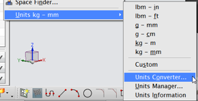
Units Converter

Instead of using a conversion function, a simple unit converter command can be executed during a command. This gives the user the value desired for the text entry field of the feature. It is a simple “constant” value for the parameter of the feature. To do this navigate to Analysis > Units > Units Converter.


Simply enter the value you have in the “From” field and select the units of the value. The “To” field immediately reports the converted value in whatever unit is selected.

Changing the Analysis Units Option


Performing a distance measurement results in a linear value in the same units as the part file by default. At any time, the analysis (measurement) units can be changed to whatever unit system is desired by executing a Simple Distance Measurement command (see below).


Then select two objects in the graphics area. A ruler and a value box appear with the value in part file units.
  • For an inch part, the default will be lbm – in.
  • For a metric part file, the default will be kg – mm.

Follow these steps to change the units:

1.    Choose Analysis->Units.
2.    Change the units from inches to millimeters.


3. Measure the length again and the popup will be in millimeters.


4. Measure the diameter of a hole… also millimeters.


Stop now and consider the ramifications…

Changing the units in the Analysis drop down has a tremendous impact on subsequent modeling functions!


Changing the Analysis Units –CHANGES THE MODELING UNITS!

Before:


After:

It should be understood that this modification of the analysis units is NOT changing the unit system of the part file, only the units in which all expressions are being created. And, as you can see above, none of the existing expressions are affected.

Default Behavior in Other Applications 

NX Assemblies are able to contain components of mixed units without lack of functionality with the exception of Working In Context – the Work Part cannot be a Component file with different units from the Displayed Assembly.

Regardless of the units of the Master Model, the Drafting Application is able to allow either inches or millimeters for:
  • The Drawing file
  • Drawing Sheet sizes (“A0, A1, A2” etc. vs “A, B, J,” etc.)
  • Drawing and View Scales
  • Dimensions (can be either or Dual Dimensioning)
CAM data is not dependent on model units.

Summary

This article discussed options that involve unit definitions, conversion, and how units can be managed.

In an engineering/manufacturing environment where unit definition is mixed, robust solutions are available. With the various methods offered by NX, however, the user must be careful and think of downstream applications that may be affected. Also, corporate standards should dictate how these methods are to be implemented to avoid confusion and errors.

Written by: 

Garrett Koch
Application Engineer
Swoosh Technologies

Wednesday, July 2, 2014

Machine housing maker directly modifies sheet metal design, increases process efficiency

Hatakeyama designs better with Solid Edge. With Solid Edge’s synchronous technology, Hatakeyama  directly modifies geometry and dramatically increasing process efficiency. Other results include near elimination of costly rework and enhanced communication between design and manufacturing groups. 

Learn how here!

Try Solid Edge free here