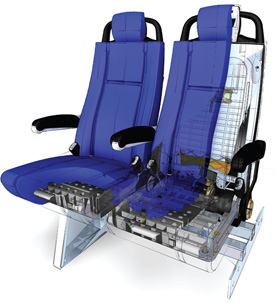
Freedman Seating designs better with Solid Edge. Moving from SolidWorks to Solid Edge improves the design process while ensuring data compatibility with customers and suppliers. Freedman now has a better ability to meet short lead times as virtual prototyping replaces physical testing. Freedman achieves more design re-use with part count down by 50 percent.
Learn more here!
Start your 45 day free trial of Solid Edge here.
Wednesday, June 25, 2014
Tuesday, June 24, 2014
Creating Macros for Customization in NX
The simplest way to customize NX is through the use of macros
A macro records a series of keystrokes in order to automate them into a simple keystroke or an icon on a custom Toolbar. Any series of keystroke a NX operator does repeatedly should be considered for a macro in order to speed up the process.
Follow these steps to create a macro:
Note: Macros have to be updated between releases.
Macros can be setup for user interaction also and can be paused to give the user instructions. Macros can be setup with user entry boxes or file selection dialog boxes.
Watch the video below to view a macro I created to change the color to green and my translucency to 75%. The video shows how I created the macro and un-did the macro’s result. The video also shows the playback of the macro created for testing.
Brian Brown
Application Engineer
Swoosh Technologies
A macro records a series of keystrokes in order to automate them into a simple keystroke or an icon on a custom Toolbar. Any series of keystroke a NX operator does repeatedly should be considered for a macro in order to speed up the process.
Follow these steps to create a macro:
- Select the tools drop down menu
- Select macro
- Select start record
Note: Macros have to be updated between releases.
Macros can be setup for user interaction also and can be paused to give the user instructions. Macros can be setup with user entry boxes or file selection dialog boxes.
Watch the video below to view a macro I created to change the color to green and my translucency to 75%. The video shows how I created the macro and un-did the macro’s result. The video also shows the playback of the macro created for testing.
Brian Brown
Application Engineer
Swoosh Technologies
Labels:
Brian Brown,
NX,
NX CAD
Location:
Harrisburg, PA, USA
Tuesday, June 17, 2014
Have a Draft and missing your original model? No problem with Solid Edge!
In Solid Edge, the draft file does not need the original model it was based off in order to open and display its information and views. So if you ever find yourself in the position where you have lost your model and all you have left is your draft, not all is lost! You can still use that information to regenerate your 3D model.
Prepping your orphan draft file
When opening the draft file disregard the dialog box about it not being able to find the model.
The off color center line surrounding all the views, is just a visual indicator that the model is missing and nothing will happen if you update the views. You can still add and remove dimensions from each of the views.
All of the information that makes up the view is still there, but you will not be able to select any lines or circles. Think of it as a ghost image. If you try to use the Create 3D command now you will only recognize the dimensions on the draft. You first need to save the draft file as a *DWG and reopen it inside Solid Edge.
Create your 3D model
With the DWG loaded, clean up the views by removing any extra hidden and center lines, crosshatching, section view text, and border items that might get in the way of the Create 3D command. You can double views to activate the block (if present) and do your deleting there, and afterwards, you will need to “Unblock” the views. (Again if present, performing this step will allow you to select the individual lines.)
Run the Create 3D command, select your *.par template, set your views, and the PAR file will be loaded. You may need line up your sketches to make it easier to create your model, but once there just use your steering wheel to re-create your part.
Watch the video below for more details!
Sam Estrada
Application Engineer
Swoosh Technologies
Prepping your orphan draft file
When opening the draft file disregard the dialog box about it not being able to find the model.
The off color center line surrounding all the views, is just a visual indicator that the model is missing and nothing will happen if you update the views. You can still add and remove dimensions from each of the views.
All of the information that makes up the view is still there, but you will not be able to select any lines or circles. Think of it as a ghost image. If you try to use the Create 3D command now you will only recognize the dimensions on the draft. You first need to save the draft file as a *DWG and reopen it inside Solid Edge.
Create your 3D model
With the DWG loaded, clean up the views by removing any extra hidden and center lines, crosshatching, section view text, and border items that might get in the way of the Create 3D command. You can double views to activate the block (if present) and do your deleting there, and afterwards, you will need to “Unblock” the views. (Again if present, performing this step will allow you to select the individual lines.)
Run the Create 3D command, select your *.par template, set your views, and the PAR file will be loaded. You may need line up your sketches to make it easier to create your model, but once there just use your steering wheel to re-create your part.
Watch the video below for more details!
Sam Estrada
Application Engineer
Swoosh Technologies
Labels:
CAD,
Drafting,
Sam Estrada,
Solid Edge
Location:
Houston, TX, USA
Tuesday, June 10, 2014
Customize Radial Menus in NX 9
Radial menus in NX are small icons that appear surrounding your cursor location; each icon can be customized to your most used features. These menus allow you to quickly and easily access features with a click and swish of your mouse. Follow the instructions below to get started customizing your NX experiences:
To access this menu in NX 9, open NX and right click on some empty space on the toolbar and click Customize.
Scroll to the bottom of the list and locate options for radial menus 1 to 3. In order to customize each menu click the box to the left of the heading.
With the first menu up while in customize mode, drag your most used features from the main menu bar into one of the eight spaces available in the radial menu. The horizontal and vertical positions on the radial menus are the easiest to access; therefore I suggest placing your most frequently used functions here.
All three radial menus can be customized using this method. I use each menu for a different set of tools (e.g. 1. Basic modeling, 2. Sketching 3. Synchronous tools).
In order to utilize the menus the 1st (left click), 2nd(Middle wheel click) and 3rd (right mouse click) must be completed while holding down Control and Shift. To make this process easier, I assign Ctrl and Shift to a function key making it very easy to instantly access any function.
Matt Beisel
Application Engineer
Swoosh Technologies
To access this menu in NX 9, open NX and right click on some empty space on the toolbar and click Customize.
Scroll to the bottom of the list and locate options for radial menus 1 to 3. In order to customize each menu click the box to the left of the heading.
With the first menu up while in customize mode, drag your most used features from the main menu bar into one of the eight spaces available in the radial menu. The horizontal and vertical positions on the radial menus are the easiest to access; therefore I suggest placing your most frequently used functions here.
All three radial menus can be customized using this method. I use each menu for a different set of tools (e.g. 1. Basic modeling, 2. Sketching 3. Synchronous tools).
In order to utilize the menus the 1st (left click), 2nd(Middle wheel click) and 3rd (right mouse click) must be completed while holding down Control and Shift. To make this process easier, I assign Ctrl and Shift to a function key making it very easy to instantly access any function.
Matt Beisel
Application Engineer
Swoosh Technologies
Labels:
Matt Beisel,
NX,
NX 9,
Radial Menus
Location:
Houston, TX, USA
Thursday, June 5, 2014
Adding Rule Based Dimension and Sensors in Solid Edge
For those designers who know exactly what the final product is going to be, these couple of Solid Edge features may not help, but those other 99% of us may need some help building intelligence into our design to facilitate future changes.
The first thing to take a look at is Rule Based Dimensions. For example, my company designs skid mounted pressure equipment. Typically these designs have a build envelope to work in. Solid Edge is a great tool to make fast changes, but what if those changes invalidate the design, and you’re not aware this happened? Here’s the formula for this D = Design, $ + dollars and : ( = wrong change so D + : ( = $$$$$$$.
You get the idea: a wrong design change typically cost lots of monies and upset bosses. SO the first thing I would do as a designer is add a Variable dimension for a rule based less than or equal to dimension to make sure my overall build stays within my envelope (Read this past post about variable tables in Solid Edge). And to add another level of control to my design we can use Sensors. Sensors allow a designer to add design intent to a model.
As in the case above, we have a skid and we have a sheet metal control box that houses all the electronics. First thing we may need is a lock on the cover. You usually have a hole in the face to allow the locking mechanism to mount to. What happens if a design change came along and said the box need to be narrower, causing the hole the lock fits into gets too close to the edge? When the part is made the guy punches the hole and deforms the sheet metal or even worse it tears along the closest edge. With a few clicks these things can be all be elevated. A simple cutout to edge Sensor can be applied so these things will pop up a warning on the screen notifying you of such conditions.
To wrap this up the old adage fits well (an ounce of prevention is worth a pound of cure). Swap cure for a wad of money, and our bosses love to hear about all the money you saved the company.
Watch this video to learn how to add rule based dimensions and sensors in Solid Edge:
Dylan Malek
Application Engineer
Swoosh Technologies
For those designers who know exactly what the final product is going to be, these couple of Solid Edge features may not help, but those other 99% of us may need some help building intelligence into our design to facilitate future changes.
The first thing to take a look at is Rule Based Dimensions. For example, my company designs skid mounted pressure equipment. Typically these designs have a build envelope to work in. Solid Edge is a great tool to make fast changes, but what if those changes invalidate the design, and you’re not aware this happened? Here’s the formula for this D = Design, $ + dollars and : ( = wrong change so D + : ( = $$$$$$$.
You get the idea: a wrong design change typically cost lots of monies and upset bosses. SO the first thing I would do as a designer is add a Variable dimension for a rule based less than or equal to dimension to make sure my overall build stays within my envelope (Read this past post about variable tables in Solid Edge). And to add another level of control to my design we can use Sensors. Sensors allow a designer to add design intent to a model.
As in the case above, we have a skid and we have a sheet metal control box that houses all the electronics. First thing we may need is a lock on the cover. You usually have a hole in the face to allow the locking mechanism to mount to. What happens if a design change came along and said the box need to be narrower, causing the hole the lock fits into gets too close to the edge? When the part is made the guy punches the hole and deforms the sheet metal or even worse it tears along the closest edge. With a few clicks these things can be all be elevated. A simple cutout to edge Sensor can be applied so these things will pop up a warning on the screen notifying you of such conditions.
To wrap this up the old adage fits well (an ounce of prevention is worth a pound of cure). Swap cure for a wad of money, and our bosses love to hear about all the money you saved the company.
Watch this video to learn how to add rule based dimensions and sensors in Solid Edge:
Dylan Malek
Application Engineer
Swoosh Technologies
Labels:
CAD,
Dylan Malek,
Solid Edge
Location:
Dallas, TX, USA
Wednesday, June 4, 2014
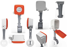
Steam accessories and control instrument maker increases design efficiency 65%
Forbes Marshall designs better with Solid Edge. Move from 2D to 3D allows company to concentrate on innovative new design work. With Solid Edge’s synchronous technology, Forbes also eliminated vendor mistakes due to drawing management issues, saved 150,000 rupees per month and increased its market share.
Learn how here!
Start your free trial of Solid Edge here.
Learn how here!
Start your free trial of Solid Edge here.
Labels:
case study,
Solid Edge,
Synchronous Technology
Location:
St. Louis, MO, USA
Thursday, May 29, 2014
Solid Edge ST7 packed with Hundreds of Customer Requested Enhancements
Solid Edge University 2014, held during the week of May 12th in Atlanta, brought the launch of Solid Edge ST7. The most powerful Solid Edge yet is updated with hundreds of enhancements requested from you, the user, that allow you to accelerate your 3D modeling, streamline your design management, power up with new apps, and enjoy a user friendly experience.
Solid Edge has always lent its hand to aiding users to design faster and ST7 is no different. 3D Sketch, available in the part, assembly and sheet metal environment, speeds up modeling by rapidly defining 3D paths for sweep operations. 3D Sketch also allows you to model pipes and wires that are bent in more than one plane, and in the assembly environ¬ment for the definition of exact paths for piping, wiring and tubing.
Solid Edge ST7 speeds up the modeling of massive assemblies. Design faster and more flexibly by duplicating components or patterning components along a curve. Performance is faster in massive assemblies and now gives users the control over the extent to which the assembly is recomputed during open and save operations.
ST7 users now have the ability to create photorealistic renderings with integration of KeyShot. KeyShot is the easiest and fastest rendering software that allows users to produce beautiful product images and processes concurrently with modeling operations. Any changes to the model are automatically updated in the rendered image using the “Live Link” capability with no need for you to reassign materials, set up animations again or update any other settings.
Solid Edge SP, a SharePoint based data management solution received a facelift in the latest release. Visualizing data and assemblies has never been easier. Quickly create workflows for task completion and show multiple property cards at once.
Solid Edge is part of a growing ecosystem of apps designed to increase productivity, manufacturing, and collaboration capabilities. These apps allow for mobile access to standard and catalog parts, automated output of models for 3D printing, expanded manufacturing abilities, cloud-based collaboration, and more. This includes CAMWorks for Solid Edge and CADENAS PartSolutions. View the apps available here.
Solid Edge ST7 brings a more intuitive user interface resulting in a faster learning curve and improved efficiency. A visual startup page provides easier access to templates, recent documents, instructional videos, the online community and standard parts. Learning paths that meet the needs of specific users are easier to access, and an improved 3D orientation “quick view cube” enables you to quickly understand model orientation and jump to common views.
Look for our What’s New in Solid Edge ST7 webinar coming soon!
Start your free trial of Solid Edge here.
Candis Spraul
PLM Marketing Specialist
Swoosh Technologies
Solid Edge has always lent its hand to aiding users to design faster and ST7 is no different. 3D Sketch, available in the part, assembly and sheet metal environment, speeds up modeling by rapidly defining 3D paths for sweep operations. 3D Sketch also allows you to model pipes and wires that are bent in more than one plane, and in the assembly environ¬ment for the definition of exact paths for piping, wiring and tubing.
Solid Edge ST7 speeds up the modeling of massive assemblies. Design faster and more flexibly by duplicating components or patterning components along a curve. Performance is faster in massive assemblies and now gives users the control over the extent to which the assembly is recomputed during open and save operations.
ST7 users now have the ability to create photorealistic renderings with integration of KeyShot. KeyShot is the easiest and fastest rendering software that allows users to produce beautiful product images and processes concurrently with modeling operations. Any changes to the model are automatically updated in the rendered image using the “Live Link” capability with no need for you to reassign materials, set up animations again or update any other settings.
Solid Edge SP, a SharePoint based data management solution received a facelift in the latest release. Visualizing data and assemblies has never been easier. Quickly create workflows for task completion and show multiple property cards at once.
Solid Edge ST7 brings a more intuitive user interface resulting in a faster learning curve and improved efficiency. A visual startup page provides easier access to templates, recent documents, instructional videos, the online community and standard parts. Learning paths that meet the needs of specific users are easier to access, and an improved 3D orientation “quick view cube” enables you to quickly understand model orientation and jump to common views.
Look for our What’s New in Solid Edge ST7 webinar coming soon!
Start your free trial of Solid Edge here.
Candis Spraul
PLM Marketing Specialist
Swoosh Technologies
Labels:
CAD,
Solid Edge,
ST7,
What's New
Location:
St. Louis, MO, USA
Subscribe to:
Posts (Atom)